RFPP 23-07558-501 Maintenance-Ready Spare for RF20 Automation
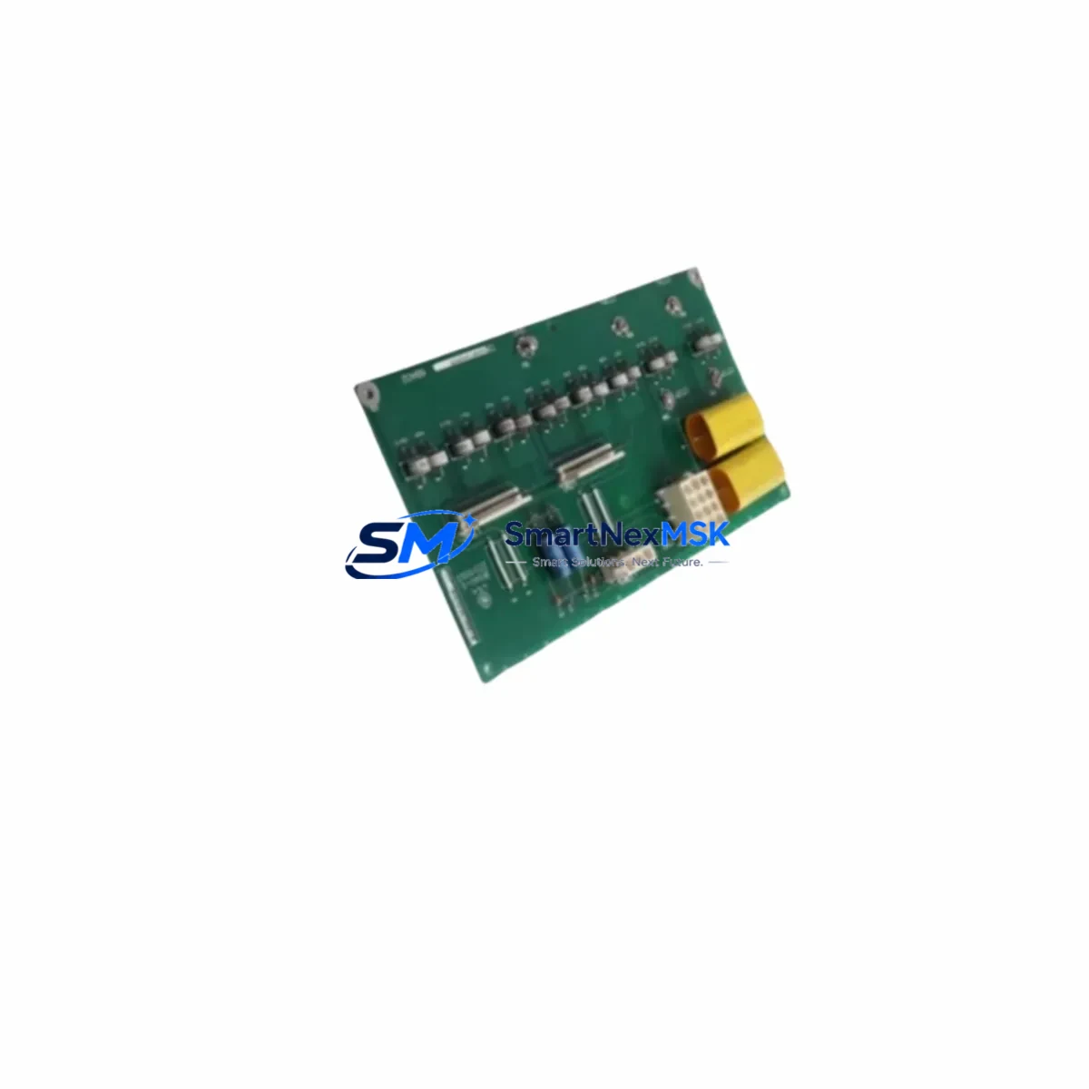
The RFPP 23-07558-501 is an original control board PCB designed for the RF Power Products RF20 series RF generator platform. As a critical spare in high-frequency industrial power systems, this board governs core generator control functions including power regulation, feedback loop management, and system protection logic. Unplanned failure of this board results in immediate generator shutdown and production downtime — making proactive spare inventory an essential element of any maintenance strategy for facilities running RF20-based plasma, semiconductor, or industrial heating processes.
This unit is sourced as an original RF Power Products component (cross-reference: 23-07557-401), fully tested prior to shipment, and backed by a 12-month warranty. It is suitable for direct field replacement in RF20 generator cabinets without firmware modification in most standard configurations. Maintenance engineers and procurement teams can rely on this spare to restore generator operation quickly and minimize unscheduled downtime.
Spare Maintenance Table
| Parameter | Specification / Detail |
|---|---|
| Part Number | RFPP 23-07558-501 |
| Cross Reference | 23-07557-401 |
| Brand | RF Power Products (RFPP) |
| Series | RF20 Generator Platform |
| Component Type | Control Board PCB |
| Function | Generator control, power regulation, protection logic, feedback management |
| Application | Plasma processing, semiconductor fab, industrial RF heating, surface treatment |
| Compatibility | RF Power Products RF20 series RF generators |
| Origin | USA |
| Unit Weight | 780 g |
| Condition | Original spare — tested before shipment |
| Installation | Direct board swap in RF20 generator cabinet; follow RFPP service manual lockout/tagout procedure |
| Operating Environment | Industrial control cabinet; observe ESD precautions during handling |
| Maintenance Interval | Inspect annually or upon generator fault/alarm events |
| Warranty | 12 months from date of shipment |
Maintenance Planning for Continuous Operation
When a maintenance or reliability engineer schedules a planned inspection or responds to an RF20 generator fault, the 23-07558-501 control board is rarely the only component that warrants attention. A thorough cabinet inspection should include the RF20 power supply module, which provides regulated DC rails to the control board — a degraded supply can cause intermittent board faults that mimic control board failure. The RF matching network and associated impedance matching controller board should also be checked, as reflected power events can stress the control PCB over time.
On the I/O side, inspect the RF20 I/O interface board and any associated signal isolation modules that condition process interlock signals before they reach the control board. Faulty isolation can introduce noise or false trips. The RF output relay assembly and RF enable relay are wear items that should be verified for contact integrity during the same maintenance window. Technicians should also check the RF20 front panel display board or HMI interface card, as communication faults between the display and control board are a common misdiagnosis when the root cause is actually a failing control PCB.
For facilities running aging RF20 systems, maintaining a small buffer stock of the 23-07558-501 control board alongside the RF20 driver board, RF20 feedback board, and key fuse assemblies (including the DC bus fuse and RF output protection fuse) is a proven strategy for reducing mean time to repair (MTTR). Terminal blocks and connector housings on the control board edge connectors should be inspected for oxidation or loose crimps, particularly in humid or chemically aggressive environments. Where the RF20 system interfaces with a host PLC or DCS via a serial communication card or DeviceNet/Profibus interface module, those communication links should be verified after any control board replacement to confirm parameter handshake integrity.
Site Replacement Workflow
Step 1 — Fault Isolation: Confirm the fault is isolated to the control board by reviewing the RF20 generator fault log and ruling out upstream power supply issues, interlock faults, and RF load anomalies. Document the fault codes before powering down.
Step 2 — Lockout/Tagout: Follow site LOTO procedures. Discharge any stored energy in the RF output circuit and DC bus capacitors per the RFPP RF20 service manual before opening the generator cabinet.
Step 3 — Board Removal: Photograph all connector positions on the existing 23-07558-501 board before disconnecting. Label edge connectors if not already marked. Remove the board using ESD-safe handling procedures.
Step 4 — Spare Installation: Install the replacement RFPP 23-07558-501 board, reconnect all harnesses in the documented positions, and verify connector seating. Confirm DIP switch or jumper settings match the removed board if applicable.
Step 5 — Commissioning: Power up in a controlled sequence per the RF20 startup procedure. Verify generator status on the front panel display, confirm no fault codes are active, and perform a low-power RF output test before returning to full process conditions.
Step 6 — Documentation: Record the replacement in the equipment maintenance log, note the new board serial number, and update the spare parts inventory. Return the failed board for failure analysis if required by site quality procedures.
This workflow supports rapid restoration of RF generator operation, typically within a single maintenance shift, and is compatible with both scheduled turnaround and emergency breakdown scenarios.
Spare Parts Support FAQ
Q1: Is the RFPP 23-07558-501 a direct replacement for 23-07557-401?
Yes. The 23-07557-401 is the cross-reference part number for this control board assembly. Both numbers refer to the same RF20 control board PCB. Confirm the board revision level with your RFPP service documentation if your generator was manufactured before 2010, as early RF20 units may require a specific revision.
Q2: How is the board tested before shipment?
Each unit undergoes functional verification prior to dispatch, including power-on self-test and output signal checks. The board is shipped in ESD-protective packaging with a test-passed label. The 12-month warranty covers defects in materials and workmanship from the date of shipment.
Q3: Can this board be used in RF20 generators from different production years?
The 23-07558-501 is designed for the RF20 platform and is compatible across the majority of RF20 generator variants. However, customers are advised to confirm the generator model number and board revision with our technical team before ordering if the system is a non-standard or customized configuration.
Q4: What is the recommended spare inventory strategy for RF20 control boards?
For facilities with two or more RF20 generators in continuous production, maintaining at least one 23-07558-501 control board as a cold spare is recommended. For single-generator critical processes, a hot-spare strategy — with the board stored in ESD packaging in the site maintenance room — minimizes exposure to extended downtime in the event of an unplanned failure.
© 2026 SMARTNEXMSK. All rights reserved.
Original Source: https://smartnexmsk.com
Contact: sales@smartnexmsk.com | +86 18259474341