Robot TZ865A BU768A390G51 Retrofit-Ready Motion Control Board: Compatible Upgrade for BU768A Series Control Systems
The Robot TZ865A BU768A390G51 is a retrofit-ready motion control board engineered for seamless integration into existing BU768A series automation platforms. As legacy motion control systems reach end-of-life and original spare parts become increasingly scarce, the TZ865A BU768A390G51 provides a verified, drop-in compatible replacement that preserves existing wiring infrastructure, program logic, and HMI screen configurations — minimizing engineering rework and unplanned downtime.
This board is purpose-built for industrial environments where control continuity is non-negotiable. Whether you are replacing a failed unit in a running production line, upgrading a discontinued motion controller in a legacy control cabinet, or migrating an aging servo drive system to a more supportable platform, the TZ865A BU768A390G51 delivers the electrical and functional compatibility required for a controlled, low-risk retrofit.
Before installation, engineers should verify the following against the existing system: power supply capacity (confirm the 24VDC or 5VDC rail can support the board’s rated draw), terminal wiring layout (cross-reference the original BU768A390G51 terminal map with the replacement board’s connector pinout), backplane interface compatibility (confirm slot type and bus protocol match the existing rack), and module address configuration (DIP switch or software address settings must be replicated from the original unit). Program compatibility should be validated in offline simulation before live commissioning, and any HMI screen bindings referencing the original module address must be updated accordingly.
Communication link integrity is equally critical during migration. If the existing system uses RS-232, RS-485, or CANopen for inter-module communication, verify that the TZ865A BU768A390G51’s communication ports are configured to match the original baud rate, parity, and station ID. On-site commissioning should include a full I/O loop check, servo axis homing verification, and a controlled test cycle before returning the line to production.
Upgrade Compatibility Table
| Parameter | Details |
|---|---|
| Compatible Series | Robot BU768A Series, TZ865A Platform |
| Replaces / Supersedes | BU768A390G51 (original), discontinued BU768A motion boards |
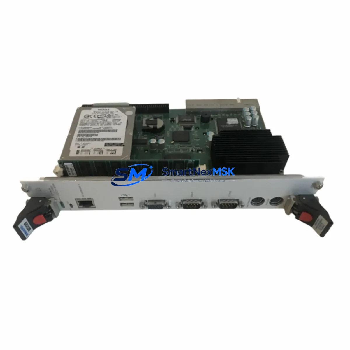
| Interface / Connector | Backplane bus connector; verify slot type against existing rack |
| Communication Compatibility | RS-232 / RS-485 / CANopen (configuration-dependent) |
| Installation Requirement | Power-off installation; DIP switch address replication required |
| Program Compatibility | Offline validation recommended before live commissioning |
| HMI Screen Update | Required if module address changes; rebind affected screen tags |
| Commissioning Steps | I/O loop check → axis homing → controlled test cycle → production |
| Warranty | 12-Month Warranty — covers manufacturing defects and functional failure |
| Outgoing Test | Function-tested before shipment; test report available on request |
Retrofit Planning for Existing Automation Systems
A successful retrofit of the TZ865A BU768A390G51 into an existing control system requires a structured approach to component mapping and staged replacement. In a typical BU768A series control cabinet, the motion control board operates alongside a coordinated set of supporting modules. The Robot BU768A power supply module must be confirmed to provide stable, within-spec DC rails before the new board is energized — an undersized or aging PSU is a common root cause of post-retrofit instability.
The BU768A series backplane rack and its associated bus termination resistors should be inspected for corrosion or mechanical damage before the replacement board is seated. If the system includes a Robot BU768A digital I/O expansion module or an analog I/O module, verify that the I/O address map remains consistent after the board swap — mismatched addresses will cause the PLC program to read incorrect process values or fail to actuate outputs.
For systems that include a Robot servo drive unit connected to the motion board via a dedicated motion bus or pulse-direction interface, the axis parameter table (acceleration ramps, position limits, encoder resolution) must be re-entered or restored from backup after the board replacement. If the original axis parameters were stored on the failed board’s internal memory rather than in the PLC program, a parameter backup from a sister machine or the original commissioning documentation will be required.
Where the control system communicates with an upstream SCADA or DCS host via Modbus RTU or a proprietary fieldbus, the communication module — such as a Robot BU768A fieldbus communication card — should be tested independently to confirm that the new motion board does not introduce address conflicts on the shared bus. A Robot programming cable (USB or RS-232 type, model-specific) will be needed to access the board’s configuration interface during commissioning.
If the system includes a Robot HMI panel or a third-party operator terminal linked to the motion controller, screen tag rebinding should be completed and validated in simulation before the HMI is reconnected to the live system. Keeping a documented record of all address changes, parameter modifications, and wiring deviations made during the retrofit is strongly recommended for future maintenance reference.
Downtime Control During System Migration
Minimizing production downtime during a motion control board replacement requires preparation that begins well before the maintenance window opens. The most effective approach is to pre-configure the replacement TZ865A BU768A390G51 offline — loading the program backup, setting module addresses, and verifying communication parameters — so that the physical swap and recommissioning can be completed within a single planned shutdown window.
Before powering down the existing system, take a full backup of the PLC program, motion axis parameters, and HMI project files. Photograph or document the existing terminal wiring, especially any field-modified connections that may not match the original drawings. Label all cables before disconnection to eliminate rewiring errors during reinstallation.
During the swap, replace only the motion control board unless other components show confirmed faults. Introducing multiple simultaneous changes increases diagnostic complexity if the system does not restart cleanly. After physical installation, perform a cold-start power-up with all field outputs disabled, verify that the board is recognized by the controller, and confirm communication link status before enabling any motion axes.
A staged recommissioning sequence — starting with I/O verification, then communication link confirmation, then axis homing in manual mode, and finally a slow-speed test cycle — allows faults to be isolated at each stage rather than discovered during full-speed production. With a pre-configured replacement board and a structured commissioning checklist, most BU768A series motion board replacements can be completed within a four-to-eight-hour planned maintenance window.
Retrofit Support FAQ
Q1: Is the TZ865A BU768A390G51 a direct drop-in replacement for the original BU768A390G51?
The TZ865A BU768A390G51 is designed as a functional replacement for the BU768A390G51 and compatible BU768A series motion boards. Connector pinout, backplane interface, and communication protocol compatibility should be verified against your specific system revision before installation. Contact our technical team with your existing board’s label information for a pre-sale compatibility confirmation.
Q2: What commissioning steps are required after installing the replacement board?
After physical installation, the recommended commissioning sequence is: (1) verify module address DIP switch settings match the original, (2) perform a cold-start power-up with outputs disabled, (3) confirm the board is recognized by the controller and communication links are active, (4) restore axis parameters from backup, (5) perform I/O loop check, (6) execute axis homing in manual mode, and (7) run a controlled test cycle before returning to production.
Q3: How do I verify wiring compatibility before installation?
Cross-reference the terminal block layout of the TZ865A BU768A390G51 with the original BU768A390G51 wiring diagram. Pay particular attention to power input terminals, encoder feedback connectors, and any field-modified wiring that may not appear in the original documentation. If wiring drawings are unavailable, our team can assist with terminal mapping based on the original board’s label and revision code.
Q4: What does the 12-month warranty cover, and is pre-shipment testing performed?
Every TZ865A BU768A390G51 unit is function-tested before shipment to verify electrical integrity and basic operational parameters. The 12-month warranty covers manufacturing defects and functional failure under normal operating conditions. A test report is available on request. Warranty claims are processed with priority support — contact sales@smartnexmsk.com with your order reference and a description of the fault.
© 2026 SMARTNEXMSK. All rights reserved.
Original Source: https://smartnexmsk.com
Contact: sales@smartnexmsk.com | +86 18259474341