Rofin S231-02 Maintenance-Ready Spare for S231 Automation
The Rofin S231-02 is an original DC servo drive and laser power controller module designed for the Rofin-Sinar S231 series laser automation systems. In industrial environments where laser cutting, welding, or marking lines must maintain maximum uptime, the S231-02 is a mission-critical component. Unplanned failure of this module can halt an entire production cell, making a verified, ready-to-ship spare part an essential element of any proactive maintenance strategy.
At SMARTNEXMSK, every Rofin S231-02 unit is sourced from original supply channels, subjected to pre-shipment functional testing, and backed by a 12-month warranty. Whether you are responding to an emergency breakdown or building a strategic spare parts inventory for a planned shutdown, we provide fast global shipping and long-term supply continuity for this model.
Spare Maintenance Table
| Parameter | Specification / Details |
|---|---|
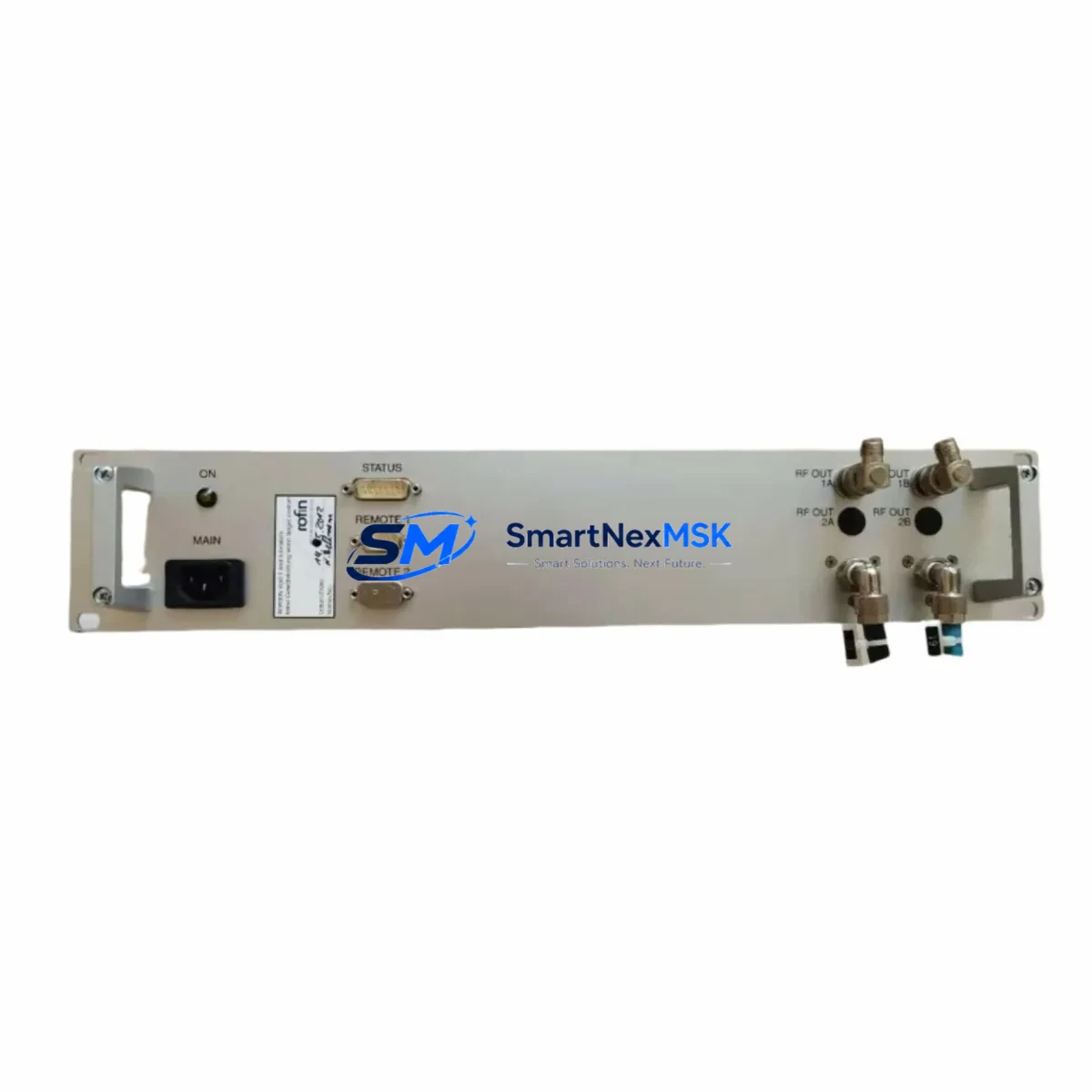
| Part Number / SKU | S231-02 |
| Brand | Rofin-Sinar |
| Series | S231 Laser Automation Series |
| Module Type | DC Servo Drive & Laser Power Controller |
| Country of Origin | Germany (DE) |
| Compatible Systems | Rofin S231 Series Laser Cutting, Welding & Marking Systems |
| Application Environment | Industrial Laser Automation, CNC Laser Cells, OEM Laser Machines |
| Installation Type | Direct replacement for original S231-02 module |
| Pre-Shipment Testing | Yes — functional verification before dispatch |
| Warranty | 12 Months |
| Condition | Original / New Old Stock / Refurbished (as available) |
| Lead Time | In-stock units ship within 1–3 business days |
| Maintenance Recommendation | Inspect every 12 months or after any laser power fault event |
Maintenance Planning for Continuous Operation
When a maintenance or procurement engineer schedules replacement of the Rofin S231-02 power controller, a thorough inspection of the surrounding electrical and control architecture is strongly recommended to prevent repeat failures and ensure full system restoration.
Begin with the DC bus power supply module that feeds the S231-02 — voltage ripple or under-voltage conditions are a leading cause of premature controller failure. Simultaneously, inspect the laser resonator interface cable assembly connecting the S231-02 to the resonator head, as insulation breakdown or connector oxidation can cause intermittent faults that mimic controller failure. The S231 series backplane or motherboard should be checked for burnt traces or failed capacitors, particularly around the power input section.
On the I/O side, verify the digital I/O expansion module associated with the laser enable and interlock signals — a faulty I/O channel can prevent the replacement S231-02 from initializing correctly. The 24 VDC auxiliary power supply feeding the control logic board should be load-tested; a marginal supply that passes no-load checks may still collapse under operational demand. Inspect all terminal blocks and DIN rail connectors in the laser control cabinet for signs of thermal stress or loose terminations, which can introduce resistance faults into the servo feedback loop.
For systems with remote monitoring, the RS-232 or RS-485 communication interface module linking the S231-02 to the supervisory HMI or SCADA panel should be verified for correct baud rate configuration and cable continuity. If the machine uses a Rofin-compatible HMI panel for laser parameter entry, confirm that the parameter set stored in the HMI matches the replacement module’s firmware version to avoid calibration mismatches after swap-out.
Additionally, check the thermal protection fuses and circuit breakers in the laser power circuit — a nuisance trip that preceded the S231-02 failure may indicate an upstream overcurrent condition that will damage the new module if left unresolved. Finally, review the signal isolation barriers on any analog laser power command signals (typically 0–10 V or 4–20 mA) to ensure clean, noise-free reference inputs to the replacement controller.
Site Replacement Workflow
Replacing the Rofin S231-02 on-site follows a structured procedure to minimize downtime and ensure system compatibility:
- Isolate and lock out the laser system at the main disconnect. Verify zero energy state on the DC bus before opening the control cabinet.
- Document the existing wiring — photograph all connector positions, cable routing, and DIP switch or jumper settings on the original S231-02 before removal.
- Remove the failed module by disconnecting all signal, power, and feedback connectors in sequence. Note any mechanical retention clips or guide rails specific to the S231 cabinet format.
- Inspect the mounting bay for debris, corrosion, or signs of thermal damage that could affect the replacement unit.
- Install the replacement S231-02, replicating all connector positions and switch settings from your documentation. Torque all terminal connections to specification.
- Power up in stages — apply auxiliary 24 VDC first, verify controller initialization and communication with the HMI, then enable the main DC bus.
- Run a low-power functional test before returning the system to full production duty. Verify laser power output linearity against the command signal.
- Update the maintenance log with the replacement date, new module serial number, and any observations from the inspection.
This workflow is compatible with both emergency breakdown replacements and planned preventive maintenance shutdowns, and is designed to keep total downtime under four hours for experienced field engineers.
Spare Parts Support FAQ
Q1: What is the expected service life of the Rofin S231-02, and when should I stock a replacement?
Under normal operating conditions in a climate-controlled laser cell, the S231-02 typically delivers 5–10 years of service. However, given that Rofin-Sinar legacy modules are no longer in active production, we recommend holding at least one spare unit on-site for any S231 series system that is critical to production continuity. Procurement lead times for obsolete modules can extend to several weeks if stock is not immediately available.
Q2: How do I verify compatibility before installing the replacement S231-02?
Confirm the part number printed on the original module’s label matches S231-02 exactly. Check the firmware revision label if present — our team can advise on cross-compatible revisions. Verify that your system’s DC bus voltage and control signal specifications match the module’s rated input range. If in doubt, contact our technical team with your machine serial number before ordering.
Q3: What pre-shipment testing does SMARTNEXMSK perform on the S231-02?
Every S231-02 unit undergoes functional power-on verification, input/output signal integrity checks, and visual inspection for component damage before dispatch. Units that do not pass testing are not shipped. A test report is available upon request for quality-critical applications.
Q4: What does the 12-month warranty cover, and how is a warranty claim handled?
The 12-month warranty covers manufacturing defects and functional failures under normal operating conditions. It does not cover damage caused by incorrect installation, overvoltage events, or physical mishandling. To initiate a warranty claim, contact sales@smartnexmsk.com with your order number, a description of the fault, and photographic evidence. Replacement or repair will be arranged within 5 business days of claim approval.
© 2026 SMARTNEXMSK. All rights reserved.
Original Source: https://smartnexmsk.com
Contact: sales@smartnexmsk.com | +86 18259474341