ROTORK 43409-03 Retrofit-Ready PCB for IQ Series Control Systems: Compatible Modernization for Legacy Actuator Platforms
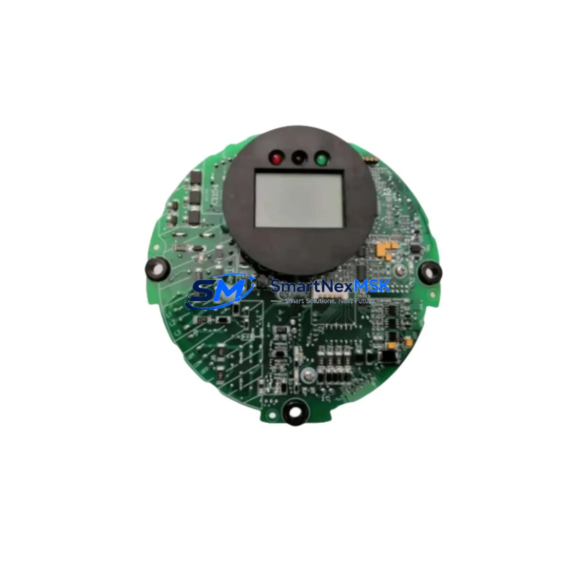
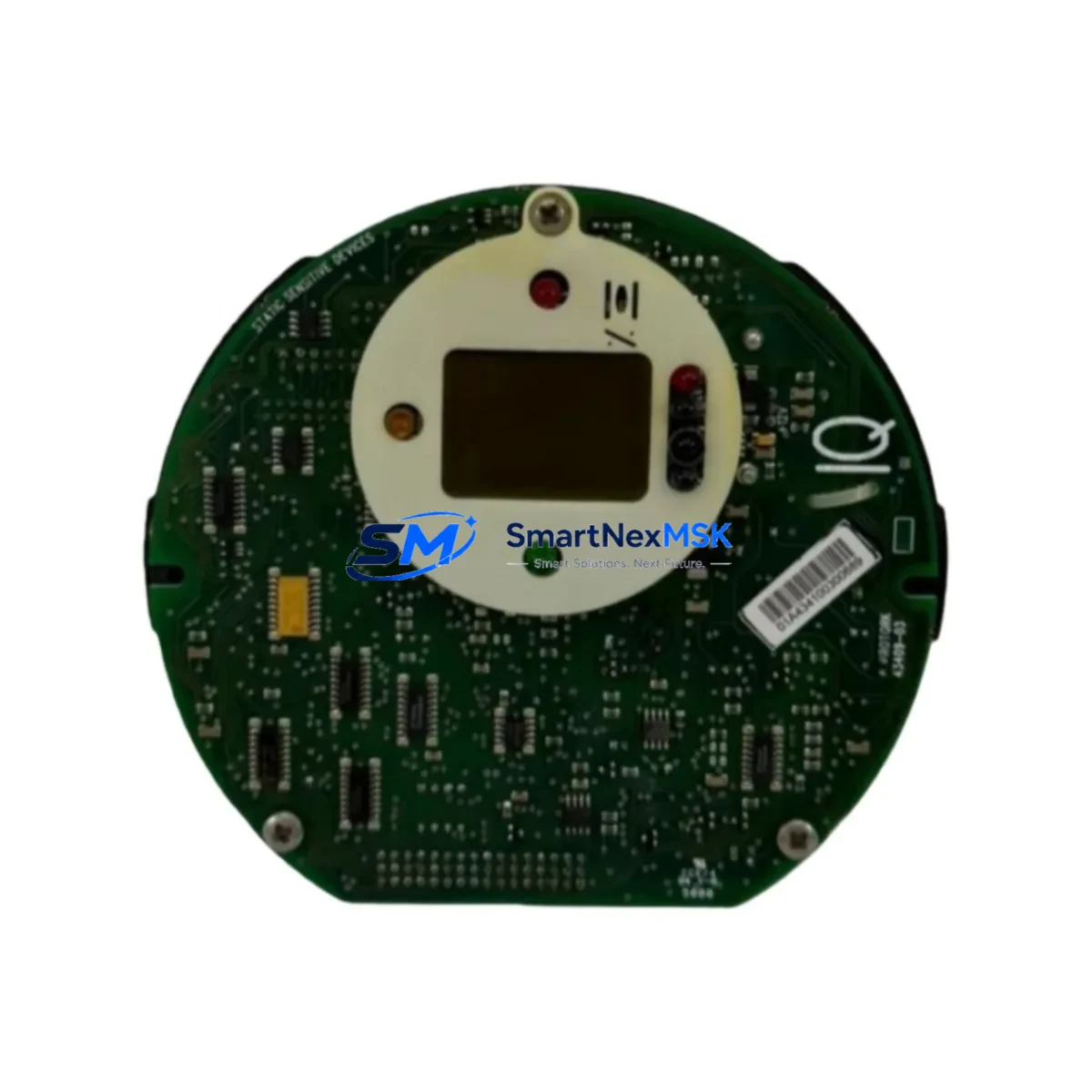
The ROTORK 43409-03 is a retrofit-ready actuator control PCB engineered for seamless integration into existing IQ Series electric actuator installations. As legacy ROTORK IQ actuator platforms approach end-of-life or encounter discontinued spare part availability, the 43409-03 provides a verified drop-in replacement path that preserves original wiring topology, terminal assignments, and communication protocol compatibility — minimizing engineering rework and unplanned downtime during system restoration or planned upgrade cycles.
Industrial facilities operating valve automation systems built around ROTORK IQ actuators — including IQ10, IQ12, IQ18, IQ25, IQ35, and IQ40 frame sizes — frequently encounter PCB-level failures caused by capacitor aging, relay contact wear, or firmware corruption. Rather than replacing the entire actuator assembly, the 43409-03 control board allows maintenance teams to restore full actuator functionality at the board level, protecting the mechanical drive train investment and avoiding the extended lead times associated with full actuator procurement.
Upgrade Compatibility Table
| Parameter | Details |
|---|---|
| Compatible Series | ROTORK IQ Series (IQ10 / IQ12 / IQ18 / IQ25 / IQ35 / IQ40) |
| Replaces / Supersedes | Legacy IQ control PCBs; discontinued ROTORK board assemblies |
| Communication Protocols | PROFIBUS DP, Modbus RTU, HART (subject to firmware variant) |
| Terminal / Wiring Compatibility | Pin-compatible with original IQ Series terminal blocks; no rewiring required under standard replacement conditions |
| Backplane / Mounting Interface | Direct board-swap; matches original PCB footprint and connector positions |
| Power Supply Requirement | 24 VDC logic supply; confirm actuator power module output before installation |
| Installation Requirement | Verify actuator enclosure rating (IP68/IP66); confirm firmware version compatibility with site SCADA/DCS |
| Commissioning Notes | Re-initialize position limits via IQ Setting Tool or Bluetooth handset after board swap; verify torque settings |
| Warranty | 12 Months from date of shipment |
| Shipping | In stock; fast global dispatch; export documentation available |
Retrofit Planning for Existing Automation Systems
Successful integration of the ROTORK 43409-03 into an existing control system requires a structured pre-installation review. Before removing the failed board, maintenance engineers should document the current actuator configuration using the ROTORK IQ Setting Tool software or the Bluetooth Setting Tool handset, capturing torque limits, position limits, control mode (local/remote/ESD), and any custom relay output assignments stored in non-volatile memory.
In multi-actuator installations where the IQ Series actuators are networked via a PROFIBUS DP segment, the replacement board must be assigned the correct PROFIBUS node address matching the original device. Address conflicts on the fieldbus segment — particularly in systems also running ROTORK Pakscan field units or third-party valve positioners — can cause communication faults that affect the entire network segment. Confirm the GSD file version used in the DCS or PLC configuration matches the firmware on the 43409-03 before going live.
For sites running Modbus RTU over RS-485, verify the baud rate, parity, and stop bit settings against the host controller configuration — whether that is a Siemens S7-300 remote I/O rack, an Allen-Bradley ControlLogix communication module, or a dedicated Modbus master card in a DCS marshalling cabinet. The 43409-03 supports standard Modbus register maps compatible with the IQ Series protocol specification, allowing existing ladder logic or function block programs to communicate without modification.
Where the actuator is integrated into a control panel alongside a ROTORK IQ-Insight display unit or a third-party HMI panel, confirm that the HMI tag database and faceplate graphics reference the correct device address and status word bit mapping. HMI screens built for the original IQ board’s status register layout will typically remain valid, but any custom diagnostic screens that read extended status bytes should be verified against the 43409-03 register map.
Power supply capacity is a critical verification point. The 43409-03 draws logic power from the actuator’s internal 24 VDC supply rail. In aging control cabinets where the ROTORK IQ power supply module has been in service for many years, it is advisable to measure the actual output voltage and ripple before installing the new board. A degraded power module — even one that kept the original board running — may not reliably support the 43409-03 under full load. If the power supply is marginal, replacing it concurrently with the control board eliminates a common source of post-retrofit instability.
For I/O-intensive applications where the actuator interfaces with a remote I/O expansion rack or a distributed I/O node — such as a Siemens ET 200S or a Rockwell 1734 POINT I/O module — verify that the discrete input and output wiring from the actuator terminal block to the I/O module remains within the original signal voltage and current specifications. The 43409-03 maintains the standard IQ Series digital I/O interface, supporting open/close/ESD command inputs and open/closed/fault status outputs without additional signal conditioning.
Downtime Control During System Migration
Minimizing process interruption during a PCB-level actuator retrofit requires careful sequencing of isolation, replacement, and recommissioning steps. The recommended approach is to perform the board swap during a planned maintenance window, with the process valve in a safe, manually-locked position. Before de-energizing the actuator, record all current position and torque data from the IQ display or via the Setting Tool, as this data will be needed to restore the actuator to its pre-fault configuration after the new board is installed.
Once the 43409-03 is seated and the actuator is re-energized, perform a bench-level functional check before reconnecting the fieldbus or hardwired control signals. Verify that the local control functions — open, close, stop — respond correctly from the actuator handwheel and local pushbuttons. Then reconnect the PROFIBUS or Modbus link and confirm that the host system recognizes the device and reads valid position feedback before returning the valve to automatic control.
In critical process applications where continuous valve position feedback is required, consider using a temporary hardwired bypass — routing the open/close command and position feedback signals through a portable relay panel — to maintain manual supervisory control of the valve during the board swap interval. This approach is particularly effective in water treatment, oil and gas, and power generation applications where even brief loss of valve position visibility is operationally unacceptable.
Pre-shipment testing of the 43409-03 includes functional verification of all I/O channels, communication interface continuity, and power supply regulation. Each unit ships with a test record confirming it has passed factory acceptance criteria, reducing the risk of installing a defective board and extending the outage window. The 12-month warranty covers manufacturing defects and component failures under normal operating conditions, providing assurance for both planned retrofits and emergency replacement scenarios.
Retrofit Support FAQ
Q1: Is the ROTORK 43409-03 a direct drop-in replacement for the original IQ Series control board?
A: Yes. The 43409-03 is designed as a pin-compatible, form-factor-matched replacement for the original ROTORK IQ Series control PCB. Under standard replacement conditions, no rewiring of the actuator terminal block is required. However, we recommend verifying the terminal assignment drawing for your specific actuator variant before installation, as some early IQ Series builds used non-standard terminal configurations.
Q2: Will my existing PROFIBUS or Modbus configuration work without changes after installing the 43409-03?
A: In most cases, yes. The 43409-03 supports the standard ROTORK IQ Series PROFIBUS DP and Modbus RTU protocol implementations. The device address, baud rate, and register map are configurable via the IQ Setting Tool and should be set to match the original board’s parameters. If your DCS or PLC uses a custom GSD file or non-standard register mapping, verify compatibility before commissioning.
Q3: What commissioning steps are required after installing the replacement board?
A: After installation, re-initialize the actuator position limits (fully open and fully closed) using the IQ Setting Tool or Bluetooth handset. Verify torque settings, control mode selection, and relay output assignments. Reconnect the fieldbus link and confirm device recognition at the host system. Perform a full open/close cycle under local control before returning to remote/automatic mode.
Q4: What does the 12-month warranty cover, and what is the return process?
A: The 12-month warranty covers manufacturing defects and component failures under normal operating and environmental conditions. It does not cover damage caused by incorrect installation, overvoltage, or physical impact. To initiate a warranty claim, contact our sales team with the order reference and a description of the fault. We will arrange return shipping and either repair or replace the unit at no charge within the warranty period.
© 2026 SMARTNEXMSK. All rights reserved.
Original Source: https://smartnexmsk.com
Contact: sales@smartnexmsk.com | +86 18259474341