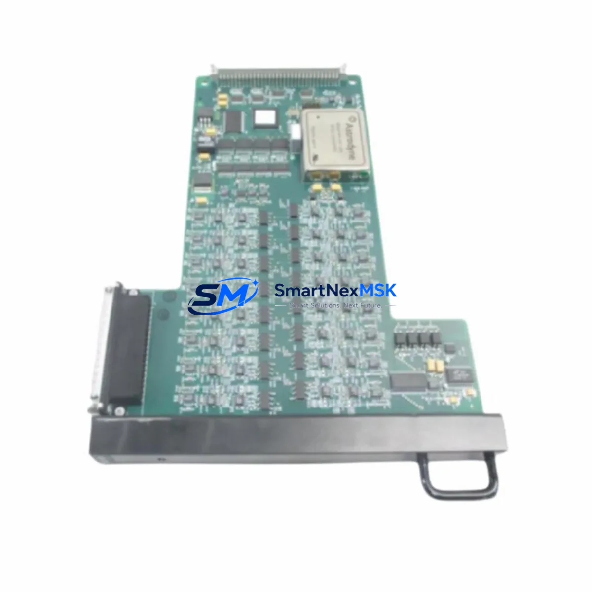
RTP 3021/00 Retrofit-Ready Analog I/O for SER 3000 Control Systems
The RTP 3021/00 is a proven analog I/O module engineered for seamless integration into RTP SER 3000 safety and control platforms. As legacy SER 3000 installations age and original spare parts become increasingly difficult to source, the 3021/00 represents one of the most reliable retrofit and replacement paths available to automation engineers managing aging distributed control infrastructure. Whether you are executing a planned system upgrade, responding to an unplanned module failure, or consolidating spare parts inventory ahead of a scheduled turnaround, the RTP 3021/00 delivers the electrical compatibility, signal accuracy, and backplane interface consistency required for a controlled, low-risk migration.
Upgrade Compatibility Table
| Parameter | Details |
|---|---|
| Compatible Platform | RTP SER 3000 Safety Control System |
| Module Type | Analog I/O Module |
| Backplane Interface | SER 3000 standard backplane slot — direct drop-in, no adapter required |
| Signal Compatibility | 4–20 mA / 0–10 V analog input/output (verify channel configuration against original I/O list) |
| Installation Requirement | Module address must be confirmed against existing rack configuration before insertion |
| Communication Compatibility | Compatible with SER 3000 internal communication bus; no protocol conversion required |
| Replacement Recommendation | Direct replacement for discontinued SER 3000 analog I/O variants; confirm firmware revision with engineering team |
| Commissioning Focus | Verify channel scaling, loop power supply, and field wiring termination before energizing |
| Warranty | 12-Month Warranty — covers manufacturing defects and functional failure under normal operating conditions |
Retrofit Planning for Existing Automation Systems
Successful integration of the RTP 3021/00 into an existing SER 3000 control cabinet begins well before the module arrives on site. Engineers should start by auditing the current rack layout and confirming available slot positions within the SER 3000 I/O chassis. The backplane power budget must be reviewed — particularly if the rack already hosts a dense mix of digital and analog modules — to ensure the power supply module, typically an RTP SER 3000 PSU, can support the additional load without triggering undervoltage conditions during peak scan cycles.
Terminal wiring is a critical checkpoint. Field cables connected to the legacy analog module must be documented, labeled, and verified against the original I/O assignment list before disconnection. In many SER 3000 installations, analog signals are routed through marshalling terminal blocks or signal conditioning barriers before reaching the module. These intermediate components should be inspected for continuity and insulation integrity as part of the replacement procedure.
Module addressing is another area that demands careful attention. The SER 3000 platform assigns logical addresses to each I/O slot, and the replacement 3021/00 must be configured to match the address of the module it replaces. Failure to align the module address will cause the SER 3000 controller — whether a dedicated safety CPU or a hybrid control processor — to flag a configuration mismatch, potentially triggering a system fault or safe-state transition.
Program compatibility should be validated in a staging environment where possible. The control logic referencing the analog channels served by the 3021/00 should be reviewed to confirm that tag names, scaling parameters, and alarm setpoints remain consistent with the replacement module’s channel characteristics. If the site uses an RTP engineering workstation or a compatible programming terminal with the SER 3000 configuration software, a full I/O force test is recommended before returning the loop to automatic control.
HMI screens that display process values sourced from the replaced analog channels should also be verified. In plants where the SER 3000 communicates with a SCADA or DCS historian via Modbus RTU, Modbus TCP, or a proprietary RTP communication driver, the data mapping tables should be cross-checked to confirm that analog values are being transmitted correctly after the module swap. Communication modules such as the RTP SER 3000 network interface card should remain undisturbed during the replacement to avoid introducing additional variables into the commissioning process.
For sites managing a broader control system modernization — for example, migrating from a legacy SER 3000 architecture toward a modern distributed control system (DCS) or a safety instrumented system (SIS) platform — the 3021/00 can serve as a bridge component, maintaining analog I/O continuity while the surrounding control infrastructure is upgraded in phases. This approach is particularly effective when combined with a structured spare parts strategy that includes stocking critical items such as SER 3000 digital output modules, analog input signal conditioners, and communication gateway modules to support the transition without extended production interruptions.
Downtime Control During System Migration
Minimizing unplanned downtime during an RTP 3021/00 module replacement requires a structured pre-outage preparation protocol. Before the maintenance window opens, the engineering team should complete a full backup of the SER 3000 controller configuration, including all I/O mapping tables, function block diagrams, and communication parameter files. This backup ensures that if an unexpected issue arises during commissioning, the system can be restored to its last known good state without extended troubleshooting delays.
During the replacement window, the affected analog loops should be placed in manual control at the field level where process safety permits. Operators should be briefed on the expected duration of the outage and the fallback procedures in place if commissioning extends beyond the planned window. The 3021/00 module should be pre-configured and bench-tested — including channel scaling verification and loop simulation using a 4–20 mA signal calibrator — before being brought to the installation site.
Once the module is installed and the rack is re-energized, a systematic channel-by-channel verification should be performed, confirming that each analog input and output is reading correctly against a known reference signal. Communication link integrity between the 3021/00 and the SER 3000 controller should be confirmed via the system diagnostic display before releasing the loops back to automatic control. With proper preparation, a single-module replacement on a SER 3000 rack can typically be completed within a two-to-four-hour maintenance window, preserving overall plant control continuity and protecting the integrity of the original program logic.
Retrofit Support FAQ
Q1: Is the RTP 3021/00 a direct drop-in replacement for the original SER 3000 analog I/O module?
A: In most SER 3000 configurations, the 3021/00 is a direct backplane-compatible replacement. However, engineers should verify the module’s channel count, signal range, and firmware revision against the original module specification sheet before installation to confirm full functional equivalence.
Q2: What wiring changes are required when installing the 3021/00 in an existing SER 3000 rack?
A: In a standard replacement scenario, no wiring changes are required at the field terminal level. Field cables connect to the same terminal positions as the original module. If the installation involves a different sub-variant of the 3021/00, confirm terminal pinout compatibility using the RTP module datasheet before proceeding.
Q3: How do I verify communication link integrity after installing the 3021/00?
A: After installation, use the SER 3000 system diagnostic interface to confirm that the module is recognized at its assigned rack address and that all analog channels are reporting valid process values. If the system communicates with an external SCADA or historian, verify that data is being received correctly at the supervisory level before closing the maintenance window.
Q4: What does the 12-month warranty cover?
A: The 12-month warranty covers manufacturing defects and functional failures under normal operating conditions from the date of shipment. Each unit undergoes pre-shipment functional testing to verify analog channel performance and backplane communication integrity. For warranty claims or technical support, contact SMARTNEXMSK directly.
© 2026 SMARTNEXMSK. All rights reserved.
Original Source: https://smartnexmsk.com
Contact: sales@smartnexmsk.com | +86 18259474341