SABO PLM500 DEB.510.00 Spare for PLM500 Automation: Spare Replacement & Industrial Downtime Risk Control
The SABO PLM500 DEB.510.00 is an original digital input (DI) module designed for the PLM500 Series programmable logic controller platform — a proven automation backbone widely deployed in process control, discrete manufacturing, and utility infrastructure. When this module fails or degrades, the consequences extend beyond a single I/O channel: the entire control loop dependent on that input signal is compromised, triggering unplanned downtime, safety interlocks, and costly production interruptions.
Sourced directly from authorized supply chains, every PLM500 DEB.510.00 unit dispatched by SMARTNEXMSK is tested before shipment and backed by a 12-month warranty. Our inventory is maintained specifically to support maintenance engineers and procurement teams who cannot afford lead-time uncertainty when a critical spare is needed on short notice.
Whether you are executing a planned overhaul, responding to an emergency fault, or building a strategic spare parts buffer for aging PLM500 installations, the DEB.510.00 is a direct, compatibility-verified replacement that restores system integrity without requiring firmware reconfiguration or hardware adaptation.
Spare Maintenance Table
| Parameter | Specification |
|---|---|
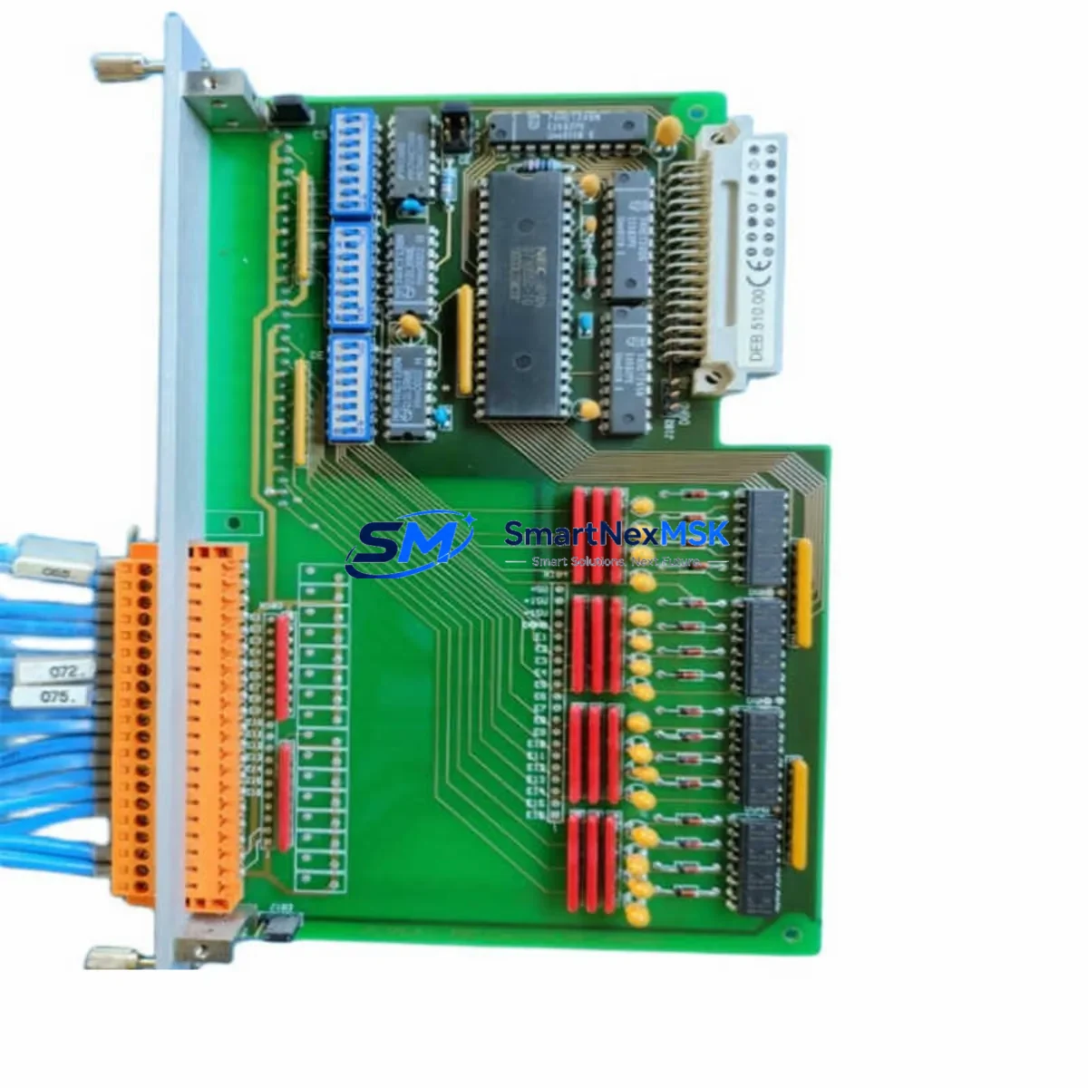
| Part Number / SKU | PLM500 DEB.510.00 |
| Brand | SABO |
| Series | PLM500 |
| Module Type | Digital Input (DI) Module |
| Product Category | PLC Digital Input Module |
| Origin | Germany (DE) |
| Compatibility | PLM500 Series PLC backplane and rack systems |
| Installation | Direct slot insertion into PLM500 rack; no hardware modification required |
| Application Environment | Industrial automation, process control, discrete manufacturing, utility infrastructure |
| Input Type | Digital (discrete) input channels |
| Pre-Shipment Testing | Yes — functional verification performed before dispatch |
| Warranty | 12 Months |
| Weight | 1,150 g |
| Supply Condition | Original spare; long-term stock availability |
Maintenance Planning for Continuous Operation
Replacing the PLM500 DEB.510.00 in the field is rarely an isolated task. Experienced maintenance engineers know that a failed digital input module is often a symptom of broader electrical stress in the control cabinet. Before returning the system to service, a thorough inspection of adjacent components is essential to prevent repeat failures and ensure signal integrity across the entire I/O loop.
Begin with the PLM500 power supply module — voltage ripple or transient spikes are a leading cause of premature DI module failure. Verify that the 24 VDC rail supplying the DEB.510.00 is within tolerance and that the power supply’s output capacitors show no signs of aging. If the installation is more than five years old, proactive replacement of the PLM500 PSU module alongside the DI module is a sound maintenance investment.
Next, inspect the terminal blocks and field wiring connected to the DEB.510.00’s input channels. Loose terminations, corroded contacts, or undersized conductors can introduce signal noise that damages input circuitry over time. Spring-clamp or screw-type terminal blocks in the same cabinet should be torque-checked and cleaned. If any signal isolators are installed between field sensors and the DI module — particularly in environments with long cable runs or high electromagnetic interference — verify their output voltage levels and isolation resistance.
The PLM500 backplane and rack assembly should be inspected for oxidation on the bus connectors. A degraded backplane connection can cause intermittent communication faults that are misdiagnosed as module failures. While the rack is accessible, check the PLM500 CPU module for firmware currency and confirm that the I/O configuration table still matches the physical slot assignments after the DEB.510.00 replacement.
For systems that include PLM500 analog input (AIB) modules in adjacent slots, verify that the analog signal references are stable — a floating common reference can induce cross-talk into digital channels. Similarly, if PLM500 relay output modules are present in the same rack, inspect the relay contacts for wear, particularly if they switch inductive loads that generate back-EMF without adequate suppression.
Communication integrity should also be confirmed: check the PLM500 communication module (Profibus, Modbus, or PROFINET variant as applicable) for error counters and verify that the network topology has not been disrupted during the maintenance window. If an HMI panel is connected to the PLM500 system, confirm that the tag database correctly reflects the restored DI channel status after the module swap.
Finally, review the cabinet’s fuse and circuit protection inventory. Blown or weakened fuses in the 24 VDC input circuit are a common collateral finding during DI module replacements. Stocking a set of replacement fuses rated for the PLM500 input circuit alongside the DEB.510.00 spare ensures that the maintenance team can complete the repair in a single intervention without a secondary parts delay.
Site Replacement Workflow
The PLM500 DEB.510.00 is designed for hot-swap or cold-swap replacement depending on the PLM500 rack configuration and site safety procedures. In most installations, the replacement sequence is as follows:
1. Isolate and document: Before removing the failed module, record the current I/O channel assignments, field wiring labels, and any LED fault codes displayed on the module face. Photograph the wiring if terminal labels are worn. Confirm with the control room that the affected input signals are in a safe state or have been bypassed in the PLC logic.
2. Remove and inspect: Extract the DEB.510.00 from its rack slot. Inspect the backplane connector pins for damage or contamination. Clean the slot with dry compressed air if debris is present.
3. Install the replacement: Insert the new PLM500 DEB.510.00 firmly into the slot until the locking mechanism engages. Reconnect field wiring to the terminal block, verifying each channel against the documented assignment. The module’s hardware address is determined by slot position — no DIP switch or jumper configuration is required in standard PLM500 installations.
4. Verify and restore: Power up the rack and confirm that the CPU module recognizes the new DI module without generating a hardware fault. Check each input channel against a known field signal source. Update the maintenance log with the replacement date, module serial number, and test results. Restore the bypassed logic and confirm normal operation with the control room.
This workflow minimizes downtime to under two hours in most scenarios, preserving system compatibility and eliminating the risk of configuration drift that can occur when substituting non-original spare parts.
Spare Parts Support FAQ
Q: Is the PLM500 DEB.510.00 available for long-term supply, or is it a one-time stock item?
A: SMARTNEXMSK maintains ongoing inventory of the PLM500 DEB.510.00 to support customers with multi-year maintenance contracts and aging PLM500 installations. We actively source from authorized channels to ensure continuous availability even as the product approaches end-of-life status with the OEM.
Q: How is compatibility with my specific PLM500 rack version verified before shipment?
A: Our technical team cross-references the SKU, hardware revision, and rack generation against the PLM500 compatibility matrix. If you provide your rack model and firmware version, we will confirm compatibility in writing before the order is processed. All units are tested against standard PLM500 backplane interfaces prior to dispatch.
Q: What does the 12-month warranty cover for the DEB.510.00?
A: The 12-month warranty covers manufacturing defects and functional failures under normal operating conditions as defined by the PLM500 Series installation guidelines. It does not cover damage resulting from incorrect installation, overvoltage events, or environmental conditions outside the module’s rated specifications. Warranty claims are processed with priority dispatch of a replacement unit.
Q: Can the PLM500 DEB.510.00 replace older DEB.510 variants without firmware changes?
A: In the majority of PLM500 installations, the DEB.510.00 is backward-compatible with earlier DEB.510 hardware revisions and does not require PLC firmware updates. However, we recommend verifying the CPU firmware version against the PLM500 release notes for your specific installation, particularly in systems running firmware versions older than three major releases. Our technical team can assist with compatibility confirmation upon request.
© 2026 SMARTNEXMSK. All rights reserved.
Original Source: https://smartnexmsk.com
Contact: sales@smartnexmsk.com | +86 18259474341