Saft LS14250 Retrofit-Ready Memory Backup for LS Series Control Systems
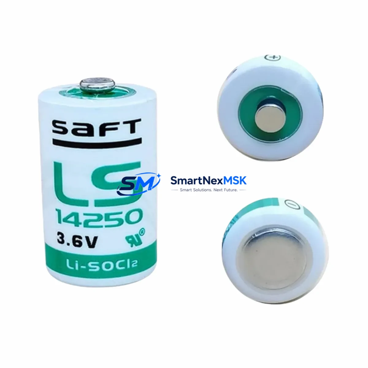
The Saft LS14250 is a 3.6V 1/2AA lithium thionyl chloride (Li-SOCl₂) battery engineered for long-term, maintenance-free memory retention in programmable logic controllers and distributed control system components. As legacy LS Series control platforms approach end-of-life and spare parts become increasingly scarce, the LS14250 has become a critical retrofit component for engineers tasked with sustaining production continuity without full system replacement.
Whether you are replacing a depleted backup cell in an aging LS Series CPU module, upgrading a control cabinet during a partial modernization project, or restoring a system after an unplanned shutdown caused by memory loss, the LS14250 provides a verified drop-in solution. Its stable 3.6V nominal voltage, ultra-low self-discharge rate, and wide operating temperature range make it the preferred choice for industrial environments where battery replacement intervals are measured in years, not months.
This listing is sourced from authorized distribution channels, ships with original Saft packaging, and is backed by a 12-month warranty covering manufacturing defects and capacity performance. Each unit undergoes pre-shipment functional testing to confirm open-circuit voltage and internal resistance compliance before dispatch.
Upgrade Compatibility Table
| Parameter | Specification / Retrofit Guidance |
|---|---|
| Chemistry | Lithium Thionyl Chloride (Li-SOCl₂) |
| Nominal Voltage | 3.6V |
| Capacity | 1200 mAh |
| Form Factor | 1/2AA (14.5mm × 25.0mm) |
| Terminal Type | Axial leads / solder tabs — confirm against host module connector type before installation |
| Compatible Series | LS Series PLC CPU modules; also compatible with select Schneider Electric TSX, Siemens S5, and Mitsubishi A-Series memory backup sockets accepting 1/2AA 3.6V cells |
| Installation Requirement | Power-off installation recommended; retain program backup via programming cable before cell removal |
| Communication Compatibility | No direct communication function; supports SRAM/Flash retention for Modbus RTU, PROFIBUS DP, and DeviceNet configured CPUs |
| Replacement Recommendation | Replace every 3–5 years or when low-battery alarm activates on CPU diagnostic panel |
| Commissioning Note | After replacement, verify program integrity via PLC programming software; re-download if memory loss is detected |
| Warranty | 12 months from shipment date — covers capacity and voltage performance under rated conditions |
Retrofit Planning for Existing Automation Systems
A successful LS Series retrofit begins well before the battery is physically replaced. Engineers should first audit the full control cabinet to identify all components sharing the same power rail and communication backbone. In a typical LS Series installation, the CPU module housing the LS14250 backup cell sits alongside discrete I/O modules, analog input/output cards, and a communication interface module — all mounted on a shared backplane or DIN-rail rack assembly. Before any intervention, document the rack slot assignments, module addresses, and I/O channel mappings to ensure post-replacement configuration accuracy.
Power supply capacity is a frequent oversight during retrofit planning. If the modernization scope extends beyond the battery to include adding new I/O expansion modules or upgrading the CPU to a higher-performance variant, the existing power supply module must be re-evaluated. Many legacy LS Series cabinets were sized with minimal headroom; adding a new Ethernet communication module or an additional analog I/O card can push the 24VDC bus beyond its rated output. Confirm total current draw against the power supply’s rated capacity before finalizing the bill of materials.
Terminal wiring compatibility is equally critical. Legacy LS Series I/O modules often use screw-terminal blocks with 2.5mm² conductor ratings. If the retrofit involves replacing an older discrete input module with a modern equivalent, verify that the new module’s terminal pitch and conductor rating match the existing field wiring. Rewiring field cables during a planned maintenance window is far less disruptive than discovering a mismatch during commissioning.
For systems where the LS Series CPU communicates with an HMI panel via RS-232 or RS-485, the communication link must be validated after the battery replacement and any associated CPU swap. HMI screen tag addresses, polling rates, and communication timeout parameters may need adjustment if the replacement CPU uses a different firmware revision. Programming cables compatible with the LS Series — typically a USB-to-RS232 adapter with the appropriate driver — should be on hand during the retrofit to allow direct program verification and re-download if needed.
Where the retrofit scope includes migrating from a legacy LS Series platform to a more current control architecture, engineers frequently encounter the need to remap I/O addresses and translate ladder logic or function block programs. In these scenarios, having a complete set of spare components — including backup CPU modules, communication cards, and terminal modules — staged and tested before the cutover window significantly reduces the risk of extended downtime. A pre-tested spare LS14250 battery should always be included in the retrofit kit as a low-cost insurance measure.
Downtime Control During System Migration
Minimizing unplanned downtime during a battery replacement or broader LS Series migration requires a structured pre-outage checklist. The most effective approach is to perform a full program backup via the PLC programming software before any hardware is touched. Save the project file to at least two independent storage locations — a local engineering workstation and a network share or USB drive — to guard against data loss during the replacement procedure.
If the LS Series CPU supports a hot-swap or battery-backed SRAM architecture, confirm whether the system allows battery replacement with the CPU powered on. Some LS Series variants permit a brief power-on replacement window of 30–60 seconds; exceeding this window risks memory corruption. For CPUs that do not support hot-swap, schedule the replacement during a planned production stop and coordinate with operations to ensure all field devices are in a safe state before the CPU is de-energized.
After the new LS14250 is installed, restore power and allow the CPU to complete its self-diagnostic cycle before attempting to re-establish communication with the HMI or SCADA system. Verify that all I/O module status LEDs indicate normal operation and that the CPU’s run/fault indicator confirms a clean startup. If the CPU enters fault mode, connect the programming cable and review the diagnostic buffer for error codes before attempting a program re-download. This systematic approach keeps the total outage window predictable and protects the integrity of the existing control logic.
For larger migration projects involving multiple control cabinets, consider a phased cutover strategy — replacing batteries and validating one cabinet at a time while the remaining cabinets continue to operate. This approach maintains partial production capacity throughout the migration and limits the blast radius of any unexpected commissioning issue.
Retrofit Support FAQ
Q1: Is the Saft LS14250 a direct drop-in replacement for the original battery in my LS Series CPU module?
In the vast majority of LS Series CPU variants, yes. The LS14250 conforms to the standard 1/2AA 3.6V Li-SOCl₂ specification used across the LS Series platform. However, some CPU modules use a connector-terminated battery holder rather than a solder-tab cell. Confirm your module’s battery holder type before ordering. If your module uses a JST or Molex connector, a pre-wired LS14250 assembly may be required.
Q2: Will I lose my PLC program if I replace the battery while the CPU is powered down?
This depends on your CPU’s memory architecture. CPUs with Flash-based program storage retain the program indefinitely without battery power; the battery only maintains real-time clock and retentive data registers. CPUs with SRAM-based program storage will lose the program if the battery is removed while the unit is de-energized. Always perform a full program backup via your programming software before replacing the battery, regardless of memory type.
Q3: How do I verify the new battery is functioning correctly after installation?
After installation, power on the CPU and navigate to the system diagnostics or battery status register in your PLC programming software. The battery voltage should read between 3.4V and 3.6V for a new LS14250. If the CPU’s low-battery alarm flag clears and the diagnostic register confirms normal battery status, the replacement is successful. For CPUs without a software-readable battery register, use a multimeter to measure the battery voltage at the holder terminals before closing the cabinet.
Q4: What warranty coverage applies to this LS14250 unit, and what does it include?
Each LS14250 unit supplied through this listing carries a 12-month warranty from the date of shipment. The warranty covers manufacturing defects, sub-specification open-circuit voltage at delivery, and premature capacity loss under rated operating conditions (−60°C to +85°C storage, −40°C to +85°C discharge). Warranty claims are processed via our sales team with proof of purchase; replacement units are dispatched within 3 business days of claim approval.
© 2026 SMARTNEXMSK. All rights reserved.
Original Source: https://smartnexmsk.com
Contact: sales@smartnexmsk.com | +86 18259474341