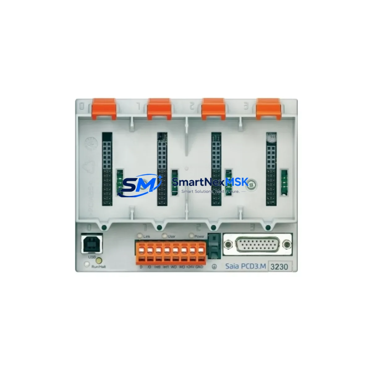
SAIA BURGESS PCD3.M3230 Retrofit-Ready CPU for PCD3 Series Control Systems
The SAIA BURGESS PCD3.M3230 is a high-performance CPU module engineered for seamless integration into existing PCD3 Series control architectures. Whether you are replacing an end-of-life controller, upgrading a legacy automation line, or restoring a critical production system after an unplanned failure, the PCD3.M3230 delivers the processing power, communication flexibility, and rack compatibility required for a smooth, low-risk transition. This module is a proven retrofit solution for industrial facilities operating SAIA BURGESS PCD3 platforms across manufacturing, building automation, water treatment, energy management, and process control environments.
Before initiating a replacement, engineers should verify several key parameters to ensure a successful cutover. Power supply capacity is the first checkpoint: confirm that the existing PCD3 power supply module — such as the PCD3.P600 or PCD3.P610 — can sustain the current draw of the PCD3.M3230 alongside all installed I/O modules and communication cards. Terminal wiring on the backplane must be inspected for compatibility; the PCD3.M3230 uses the standard PCD3 rack connector pinout, but any field-wired terminal blocks connected to adjacent I/O modules such as the PCD3.E110 digital input module or PCD3.A460 analog output module should be documented and verified before removal of the old CPU.
Backplane interface compatibility is a critical factor in PCD3 retrofit projects. The PCD3.M3230 is designed to seat directly into PCD3 rack assemblies including the PCD3.C100 and PCD3.C200 rack configurations. Module addressing must be re-confirmed after installation: slot assignments for I/O modules, communication processors, and special function cards must match the address map defined in the original PG5 project file. Any deviation in slot addressing will cause the CPU to fault on startup and may require a full hardware configuration rebuild in SAIA PG5 programming software.
Program compatibility is another area requiring careful attention. Projects developed for earlier PCD3 CPU variants can generally be recompiled and downloaded to the PCD3.M3230 without structural changes, but engineers should review all hardware-dependent function blocks, particularly those referencing specific memory areas, retentive data zones, or real-time clock functions. Communication links using S-Bus, Modbus RTU, Modbus TCP/IP, or BACnet MS/TP should be re-tested after the CPU swap to confirm that baud rates, node addresses, and protocol parameters have been correctly restored. If the system includes a PCD7.D series HMI panel connected via S-Bus or Ethernet, the HMI project should be validated against the new CPU’s variable table to ensure all data point mappings remain intact.
For systems that include a PCD3.F27x communication processor card handling Profibus DP or other fieldbus protocols, the GSD file configuration and slave address assignments must be preserved and re-verified post-installation. Similarly, if the control cabinet includes a PCD3.T665 or similar timer/counter module, its configuration registers should be backed up before the CPU is removed.
Upgrade Compatibility Table
| Parameter | Details |
|---|---|
| SKU / Part Number | PCD3.M3230 |
| Brand | SAIA BURGESS |
| Series | PCD3 |
| Module Type | PLC CPU Module |
| Rack Compatibility | PCD3.C100, PCD3.C200 rack systems |
| Communication Interfaces | S-Bus, Modbus RTU, Modbus TCP/IP, BACnet MS/TP |
| Programming Software | SAIA PG5 (all current versions) |
| Power Supply Compatibility | PCD3.P600, PCD3.P610 |
| Installation Type | Direct backplane slot replacement |
| Replacement Scope | Drop-in for discontinued PCD3 CPU variants |
| Commissioning Requirement | PG5 project re-download + I/O address verification |
| HMI Compatibility | PCD7.D series panels via S-Bus / Ethernet |
| Origin | Switzerland |
| Warranty | 12 Months |
Retrofit Planning for Existing Automation Systems
A successful PCD3.M3230 retrofit begins with a thorough site survey of the existing control cabinet. Document all installed modules in the PCD3 rack: record the slot position, part number, and firmware version of every component including digital I/O modules such as the PCD3.E110 and PCD3.A460, the power supply module (PCD3.P600 or PCD3.P610), any installed communication processor cards (PCD3.F27x series), and any special function modules. Photograph the terminal wiring on all field-connected I/O modules before disconnecting anything.
Back up the complete PG5 project from the existing CPU using the PG5 online backup function. Verify that the backup includes all program blocks, hardware configuration, symbol tables, and retentive data definitions. If the system uses a PCD7.D HMI panel, export the HMI project as well. For systems with Modbus TCP/IP or BACnet integration, export the communication configuration and note all IP addresses, node IDs, and register maps.
During the physical swap, power down the cabinet in the correct sequence: disable field outputs first, then shut down the CPU, then remove power from the PCD3.P600 supply. Seat the PCD3.M3230 into the same rack slot as the original CPU. Restore power and allow the module to complete its self-test sequence before attempting a PG5 connection. Download the backed-up project, perform a full hardware configuration compile, and verify that all I/O modules are recognized correctly in the PG5 hardware configurator.
After the program download, test each I/O channel systematically: force digital outputs through the PCD3.E110 output modules, verify analog signal scaling on the PCD3.A460 channels, and confirm that all communication links — including any Profibus DP slaves managed by a PCD3.F27x card — are online and responding. If a PCD7.D HMI is connected, navigate through all HMI screens to confirm that data values are updating correctly and that no unresolved variable references exist.
Downtime Control During System Migration
Minimizing production downtime during a PCD3.M3230 CPU replacement requires advance preparation and a disciplined cutover procedure. The most effective approach is to pre-configure and bench-test the replacement module before the scheduled maintenance window. Load the PG5 project onto the PCD3.M3230 in a workshop environment, simulate I/O responses where possible, and verify that the communication configuration compiles without errors.
During the cutover window, follow a strict sequence: complete the PG5 backup from the live CPU, power down the cabinet, perform the physical module swap, restore power, download the pre-tested project, and execute a structured I/O checkout before returning the system to automatic mode. Keep the original CPU module on-site as a fallback until the replacement has been validated through at least one full production cycle. Document all changes to the hardware configuration, program version, and communication parameters for the site maintenance record.
For systems where even brief interruptions are critical, consider staging the PCD3.M3230 in a parallel test rack using a PCD3.C100 chassis with representative I/O modules to validate the full program logic before the live cutover. This approach allows engineers to identify any program compatibility issues, address mapping conflicts, or communication timing problems without impacting the production line. Retentive data values — particularly setpoints, counters, and recipe parameters stored in the original CPU — should be recorded manually or exported via PG5 data logging before the swap to allow rapid restoration after the new CPU is online.
Retrofit Support FAQ
Q: Is the PCD3.M3230 a direct drop-in replacement for older PCD3 CPU modules?
A: Yes. The PCD3.M3230 uses the standard PCD3 backplane connector and is physically compatible with PCD3.C100 and PCD3.C200 rack assemblies. A PG5 project re-download and hardware configuration verification are required after installation. No mechanical modifications to the rack or cabinet are needed.
Q: Do I need to rewire any terminals when replacing the CPU with a PCD3.M3230?
A: Field wiring connected to I/O modules such as the PCD3.E110 or PCD3.A460 does not need to be disturbed, as these modules remain in their rack slots during the CPU swap. Only the CPU slot is affected. Verify that the power supply module (PCD3.P600 / PCD3.P610) output capacity covers the PCD3.M3230 current draw before powering up.
Q: Will my existing Modbus TCP/IP and S-Bus communication links work after installing the PCD3.M3230?
A: Communication protocols supported by the PCD3.M3230 include S-Bus, Modbus RTU, Modbus TCP/IP, and BACnet MS/TP. After the CPU swap and project download, re-test all communication links by verifying node addresses, baud rates, and IP settings match the original configuration. HMI panels (PCD7.D series) connected via S-Bus or Ethernet should be validated by cycling through all screens and confirming live data updates.
Q: What warranty is provided, and is pre-shipment testing performed?
A: Every PCD3.M3230 unit is covered by a 12-month warranty from the date of shipment. Prior to dispatch, each module undergoes functional testing to verify power-on self-test completion, backplane interface integrity, and communication port operation. Units are shipped with protective packaging suitable for international freight. Contact our team for expedited shipping options if your application requires urgent replacement stock.
© 2026 SMARTNEXMSK. All rights reserved.
Original Source: https://smartnexmsk.com
Contact: sales@smartnexmsk.com | +86 18259474341