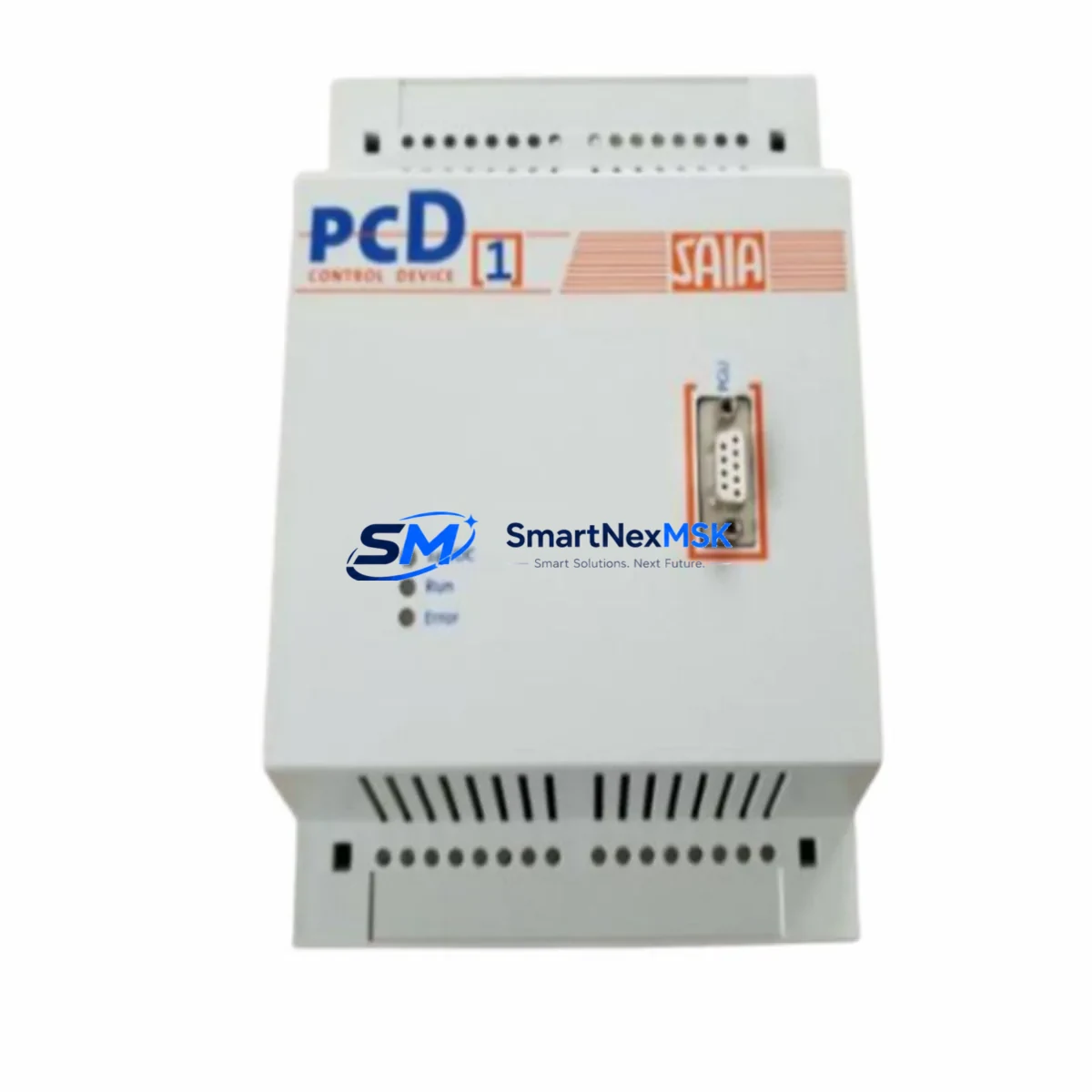
SAIA PCA1.M41M4 Retrofit-Ready Processor for PCD1 Control Systems
The SAIA PCA1.M41M4 is a compact PLC processor module engineered for the SAIA PCD1 Series control platform. As legacy PCD1 installations reach end-of-service milestones, this module serves as the primary retrofit and drop-in replacement solution for facilities managing aging automation infrastructure. Whether you are upgrading a discontinued control cabinet, recovering from an unplanned processor failure, or executing a planned modernization of a multi-zone HVAC, water treatment, or manufacturing line, the PCA1.M41M4 delivers verified compatibility with existing PCD1 backplane architectures and I/O configurations.
Each unit supplied by SMARTNEXMSK is sourced from authorized distribution channels or certified refurbishment partners, function-tested prior to dispatch, and covered by a 12-month warranty. Stock is maintained to support both emergency replacement orders and scheduled retrofit projects.
Upgrade Compatibility Table
| Parameter | Details |
|---|---|
| Compatible Series | SAIA PCD1 (PCD1.M110, PCD1.M120, PCD1.M130 backplane variants) |
| Replaces / Supersedes | PCA1.M41M4 (direct), compatible with PCD1 processor slot positions |
| Backplane Interface | PCD1 standard bus connector; verify slot 0 processor position before installation |
| Communication Compatibility | S-Bus (SAIA proprietary), RS-232, RS-485; confirm firmware revision matches existing HMI and SCADA configuration |
| Installation Requirement | DIN rail mount; power-off installation mandatory; confirm 24 VDC supply capacity ≥ module rated draw |
| Retrofit Recommendation | Back up existing program via PG5 programming software before removal; verify I/O module addresses post-swap |
| Commissioning Focus | Re-establish S-Bus node address; validate analog and digital I/O scan cycle; confirm HMI tag mapping |
| Warranty | 12 months from date of shipment; covers manufacturing defects and functional failure under normal operating conditions |
Retrofit Planning for Existing Automation Systems
A successful PCA1.M41M4 retrofit begins well before the replacement unit arrives on site. Engineers responsible for the upgrade should first audit the existing PCD1 rack configuration, documenting the slot assignments of all installed I/O modules — including digital input modules such as the PCD1.W200, analog output modules, and any specialty communication cards occupying the expansion slots. The processor’s memory map and I/O address table must be exported from the current system using SAIA PG5 programming software before the old processor is removed.
Power supply capacity is a critical pre-installation checkpoint. The existing PCD1 power supply module — typically a 24 VDC regulated unit — must be verified to provide sufficient current headroom for the replacement processor plus all connected I/O modules. If the original power supply is undersized or shows signs of aging, concurrent replacement with a new PCD1-compatible PSU is strongly recommended to avoid nuisance trips after commissioning.
Terminal wiring on the PCD1 platform is generally preserved during a processor swap, as the I/O modules remain in place. However, engineers should inspect all field wiring terminations on PCD1 terminal base units for corrosion, loose connections, or insulation degradation — conditions that are common in installations exceeding ten years of service. Any suspect terminations should be re-torqued or replaced before the new processor is powered on.
Communication link continuity is another area requiring careful attention. If the existing system uses S-Bus over RS-485 to connect to a SAIA PCD7 HMI panel or a third-party SCADA system, the node address and baud rate settings stored in the original processor must be replicated exactly in the replacement unit. Mismatched S-Bus parameters are among the most common causes of extended commissioning delays in PCD1 retrofit projects. Where the site uses Modbus RTU or Modbus TCP via an add-on communication module such as the PCD7.F110, the gateway configuration should be exported and re-imported after the processor swap.
For systems that include PCD1 analog input modules handling 4–20 mA process signals from field transmitters, the engineering team should confirm that the analog scaling parameters embedded in the PLC program are intact after the program download to the new PCA1.M41M4. A channel-by-channel live signal verification against the SCADA historian or HMI trend display is the most reliable method to confirm correct analog I/O operation before returning the system to automatic control.
Where the retrofit scope extends beyond a single processor replacement — for example, when upgrading an entire control cabinet that also includes a PCD1 expansion rack, additional PCD1.W300 digital output modules, or a PCD7 operator panel — a phased commissioning plan with defined hold points and sign-off criteria will minimize the risk of undetected configuration errors propagating into live production.
Downtime Control During System Migration
Minimizing unplanned downtime is the primary operational constraint in any PCD1 processor replacement. The recommended approach is to perform the swap during a scheduled maintenance window, with a target total outage of under two hours for a standard single-rack PCD1 installation. The following sequence has been validated across multiple retrofit projects:
Step 1 — Pre-shutdown preparation: Upload the current PLC program from the existing processor to a laptop running PG5. Verify the uploaded file against the last known good backup. Document all S-Bus node addresses, communication port settings, and I/O force tables currently active in the system.
Step 2 — Controlled shutdown: Place the process under manual control at the field level where possible. Notify upstream and downstream systems — including any connected SAIA PCD2 or PCD3 controllers on the same S-Bus network — that the node will be temporarily offline. Power down the PCD1 rack in the correct sequence: field power first, then control power.
Step 3 — Module swap: Remove the existing processor from slot 0. Install the PCA1.M41M4 replacement. Confirm the module is fully seated on the backplane connector. Restore control power only — do not re-energize field outputs at this stage.
Step 4 — Program download and parameter restore: Connect the programming cable to the PCA1.M41M4 service port. Download the verified program file. Restore S-Bus node address and communication parameters. Confirm the processor enters RUN mode without fault flags.
Step 5 — I/O verification and return to service: Re-energize field power. Perform a structured I/O check — digital inputs first, then digital outputs under manual command, then analog channels. Confirm HMI displays are updating correctly. Return the system to automatic control and monitor for one full process cycle before closing the maintenance window.
Having a pre-tested spare PCA1.M41M4 on the shelf — sourced and function-tested in advance — is the single most effective measure for protecting against extended unplanned outages in aging PCD1 installations.
Retrofit Support FAQ
Q1: Is the PCA1.M41M4 a direct drop-in replacement for the original SAIA PCD1 processor?
Yes. The PCA1.M41M4 is designed for the PCD1 processor slot and is compatible with the standard PCD1 backplane bus. No mechanical modification to the rack is required. The existing I/O modules, terminal bases, and field wiring remain in place. A program download via PG5 is required after installation.
Q2: What commissioning steps are required after installing the replacement processor?
After installing the PCA1.M41M4, you must download the PLC program, restore S-Bus node address and communication port settings, verify all I/O channels against live field signals, and confirm HMI tag mapping is functioning correctly. For systems with analog I/O, a full channel scaling verification is recommended before returning to automatic control.
Q3: How do I confirm wiring and terminal compatibility before installation?
The PCA1.M41M4 does not have direct field wiring connections — all field I/O is handled by the installed I/O modules in the PCD1 rack. Terminal wiring compatibility is therefore determined by the existing I/O modules, not the processor. Inspect terminal block connections on all I/O modules for condition and torque before powering the replacement processor.
Q4: What does the 12-month warranty cover, and how is it claimed?
The 12-month warranty covers manufacturing defects and functional failure under normal operating conditions from the date of shipment. It does not cover damage resulting from incorrect installation, overvoltage, or environmental conditions outside the module’s rated specifications. To initiate a warranty claim, contact SMARTNEXMSK at sales@smartnexmsk.com with your order reference, a description of the fault, and photographic evidence of the installation. Replacement or repair will be arranged within the warranty period.
© 2026 SMARTNEXMSK. All rights reserved.
Original Source: https://smartnexmsk.com
Contact: sales@smartnexmsk.com | +86 18259474341