Schenck VMD20150.xx V003853.B11 Spare Disocont Automation: Spare Replacement & Industrial Downtime Risk Control
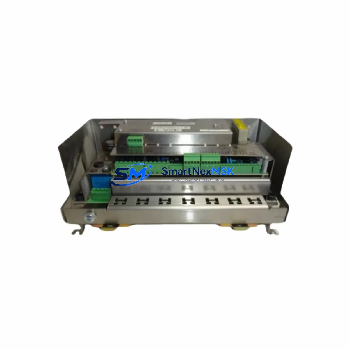
The Schenck Process VMD20150.xx V003853.B11 is an original weighfeeder controller module from the Disocont series — a proven platform widely deployed in bulk material handling, cement, mining, and chemical processing plants worldwide. When this controller fails or degrades, the entire weighfeeder loop is compromised, leading to process interruptions, inaccurate dosing, and unplanned downtime. Sourcing a verified, tested spare unit is the fastest path to restoring continuous operation.
This listing provides a maintenance-ready, original-specification VMD20150.xx V003853.B11 unit, fully inspected and tested prior to shipment. It is suitable for direct replacement in existing Disocont weighfeeder control cabinets without firmware reconfiguration in most standard installations. Each unit ships with a 12-month warranty covering manufacturing defects and functional integrity.
Spare Maintenance Table
| Parameter | Specification / Detail |
|---|---|
| Part Number | VMD20150.xx V003853.B11 |
| Full SKU | VMD20150.xx V003853.B11 VMD20150 |
| Brand | Schenck Process |
| Series | Disocont Weighfeeder Controller |
| Product Type | Weighfeeder Controller Module |
| Country of Origin | Germany (DE) |
| Compatibility | Disocont series weighfeeder control systems; replaces legacy VMD20150 variants |
| Application Environment | Industrial bulk material handling, cement plants, mining, chemical processing |
| Installation | DIN-rail or panel-mount in standard Disocont control cabinet |
| Communication Interface | Compatible with Disocont fieldbus and serial communication protocols (PROFIBUS, RS-485 per system config) |
| Power Supply | 24 VDC nominal (verify with cabinet power supply module before installation) |
| Warranty | 12 Months — covers manufacturing defects and functional performance |
| Pre-shipment Testing | Full functional test performed; unit verified operational before dispatch |
| Condition | Original spare — new or refurbished to OEM specification |
| Lead Time | In-stock units ship within 3–5 business days; contact for urgent requirements |
| Maintenance Recommendation | Inspect every 12 months; replace on first sign of calibration drift or communication fault |
Maintenance Planning for Continuous Operation
Replacing the VMD20150.xx V003853.B11 controller is rarely an isolated task. Maintenance engineers and procurement engineers working on Disocont-based weighfeeder systems should treat this replacement as an opportunity to audit the entire control loop. A controller fault is frequently preceded or accompanied by degradation in adjacent components.
Begin with the 24 VDC power supply module feeding the Disocont cabinet — voltage ripple or under-voltage conditions are a leading cause of controller resets and communication errors. Verify output voltage under load before commissioning the replacement VMD20150.xx unit. Alongside the power supply, inspect the terminal blocks and field wiring connected to the load cell signal inputs; corroded or loose terminals introduce measurement noise that can be misdiagnosed as a controller fault.
The load cell junction box and its associated signal conditioning module (such as the Disocont VMD20xxx-series analog input card) should be checked for moisture ingress and zero-point drift. If the weighfeeder has been in service for more than five years, consider replacing the load cell amplifier board at the same maintenance interval as the VMD20150.xx controller to avoid a repeat callout.
For systems using PROFIBUS DP or Modbus RTU communication to a PLC or DCS, verify the fieldbus communication module and its termination resistors. A degraded bus terminator can cause intermittent communication faults that appear as controller errors. Similarly, inspect the I/O expansion modules connected to the Disocont backplane — particularly digital output cards driving belt speed control relays and alarm outputs.
The speed sensor (tacho) input circuit is another critical checkpoint: a worn proximity sensor or broken tacho cable will cause belt speed errors that the VMD20150.xx controller cannot compensate for, leading to false overload or underload alarms. Replace the speed sensor if signal frequency is unstable. Finally, review the HMI operator panel or remote display unit connected to the Disocont system — firmware compatibility between the new controller revision (B11) and the existing HMI should be confirmed before go-live to avoid parameter display errors.
Keeping a stocked spare of the VMD20150.xx V003853.B11, along with a backup EEPROM or parameter file of the current weighfeeder calibration, is the single most effective strategy for reducing mean time to repair (MTTR) on Disocont-based systems.
Site Replacement Workflow
Step 1 — Isolate and document: De-energize the Disocont control cabinet following your site LOTO procedure. Before removing the VMD20150.xx module, photograph or record all wiring connections, DIP switch settings, and the current parameter set from the HMI or engineering software. Export the calibration file if your system supports it.
Step 2 — Remove the legacy module: Disconnect field wiring and bus connectors in sequence. Note the firmware version label on the outgoing unit — confirm the replacement V003853.B11 revision is compatible with your system’s existing software version. In most Disocont installations, the B11 hardware revision is backward-compatible with earlier VMD20150 variants, but always verify against your system documentation.
Step 3 — Install the replacement unit: Seat the VMD20150.xx V003853.B11 into the cabinet slot, reconnect all field wiring and bus connectors, and restore power. The controller will perform a self-test on startup. Monitor the status LEDs for fault codes before proceeding.
Step 4 — Restore parameters and calibrate: Load the saved parameter file or re-enter calibration data manually via the HMI. Perform a static zero-point check and a dynamic span check with a known test weight before returning the weighfeeder to service. Document the commissioning results for your maintenance records.
Step 5 — Verify system integration: Confirm PROFIBUS or Modbus communication is re-established with the upstream PLC or DCS. Check that all analog outputs (belt load, belt speed, throughput rate) are reading correctly at the control room level. Run the weighfeeder at minimum and maximum feed rates to validate the full operating range before handover.
This structured replacement workflow minimizes downtime, ensures system compatibility, and provides a documented audit trail for maintenance records and regulatory compliance.
Spare Parts Support FAQ
Q1: Is the VMD20150.xx V003853.B11 a direct drop-in replacement for earlier VMD20150 hardware revisions?
In the majority of Disocont installations, the B11 hardware revision is fully backward-compatible with earlier VMD20150 variants. However, we recommend verifying the firmware version of your existing HMI and engineering software against the B11 hardware specification before installation. Contact our technical team with your system serial number for a compatibility confirmation prior to ordering.
Q2: What pre-shipment testing is performed on each unit?
Every VMD20150.xx V003853.B11 unit undergoes a full functional test before dispatch, including power-on self-test verification, communication interface check, and analog I/O signal validation. Units that do not pass all test criteria are not shipped. A test report is available upon request for quality-critical procurement processes.
Q3: How should I manage spare parts inventory for long-term Disocont system support?
For plants operating multiple Disocont weighfeeder lines, we recommend maintaining at least one VMD20150.xx controller as a hot spare per production line. Given that Schenck Process has transitioned some Disocont variants to end-of-life status, securing additional spare units now protects against future supply constraints. We offer long-term supply agreements and reserved stock programs for high-volume or critical-process customers.
Q4: What does the 12-month warranty cover, and what is the claims process?
The 12-month warranty covers all manufacturing defects and functional failures under normal operating conditions. It does not cover damage caused by incorrect installation, overvoltage events, or physical mishandling. To initiate a warranty claim, contact our sales team with the order reference, a description of the fault, and photos of the unit and installation. We will arrange return shipping and provide a replacement or repair within an agreed lead time.
© 2026 SMARTNEXMSK. All rights reserved.
Original Source: https://smartnexmsk.com
Contact: sales@smartnexmsk.com | +86 18259474341