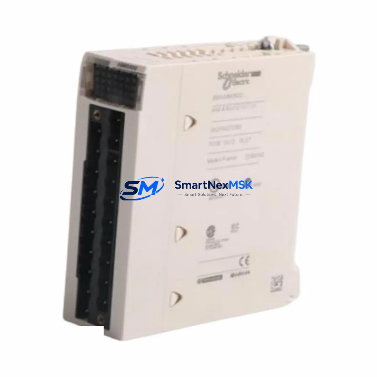
SCHLEICHER SCTUST21 Maintenance-Ready Spare for Quantum Automation
The SCHLEICHER SCTUST21 is an original communication module designed for the Quantum series PLC platform — one of SCHLEICHER’s most widely deployed automation architectures in process control, machine tool, and discrete manufacturing environments. For maintenance engineers managing aging control systems, the SCTUST21 represents a critical link between the CPU backplane and field communication networks. Unplanned failure of this module can halt an entire production line, making verified spare availability a non-negotiable element of any serious maintenance strategy.
At SMARTNEXMSK, every SCTUST21 unit is sourced from authorized supply chains, individually inspected, and function-tested prior to dispatch. We maintain buffer stock specifically to support emergency replacement scenarios — same-day processing is available for in-stock orders. Whether you are executing a planned shutdown, responding to a fault alarm, or building a strategic spare parts inventory for a multi-line facility, the SCTUST21 is shipped with full documentation and a 12-month warranty covering manufacturing defects and functional failure under normal operating conditions.
This module is engineered for direct drop-in replacement within compatible Quantum-series control cabinets. No firmware re-flashing or rack reconfiguration is required in standard replacement scenarios, significantly reducing mean time to repair (MTTR) and minimizing the risk of configuration errors during high-pressure downtime events.
Spare Maintenance Table
| Parameter | Specification / Value |
|---|---|
| Part Number / SKU | SCTUST21 |
| Brand | SCHLEICHER |
| Series | Quantum PLC Platform |
| Module Type | PLC Communication Module |
| Country of Origin | Germany (DE) |
| Mounting | DIN rail / Quantum backplane slot |
| Communication Interface | Serial / fieldbus (Quantum-series compatible) |
| Operating Voltage | 24 VDC (backplane supplied) |
| Operating Temperature | 0°C to +55°C |
| Storage Temperature | -25°C to +70°C |
| Humidity | 5–95% RH, non-condensing |
| Protection Class | IP20 (cabinet-mounted) |
| Weight | 2,920 g (packaged) |
| Compatibility | SCHLEICHER Quantum series racks and CPUs |
| Replacement Scope | Direct drop-in; no rack reconfiguration required |
| Pre-shipment Testing | Function-tested, inspected, documented |
| Warranty | 12 Months — manufacturing defects & functional failure |
| Lead Time | In stock — same-day dispatch available |
| Maintenance Recommendation | Inspect connector pins and backplane contacts at each planned shutdown; replace if communication errors persist after reseating |
Maintenance Planning for Continuous Operation
When a SCTUST21 communication module is flagged for replacement, experienced maintenance engineers treat the event as a trigger for a broader cabinet inspection — not an isolated swap. The communication module sits at the intersection of the CPU, the I/O bus, and the field network, meaning a failure here often masks or is caused by adjacent component degradation.
Begin by verifying the 24 VDC backplane power supply output — a marginal power rail is a common root cause of intermittent communication faults that are incorrectly attributed to the module itself. If the rack houses a dedicated SCHLEICHER power supply module (such as those in the Quantum PSU family), check its output voltage under load before installing the replacement SCTUST21.
Next, inspect the backplane bus connector and the slot contacts for oxidation or mechanical damage. In high-humidity or chemically aggressive environments, connector corrosion can cause the same fault signatures as a failed module. A replacement module installed into a corroded slot will fail prematurely.
Review the I/O modules adjacent to the communication slot — particularly any digital input/output modules or analog signal modules sharing the same rack segment. A shorted I/O channel can inject noise onto the backplane bus, degrading communication integrity. If the system uses signal isolators between field sensors and the I/O rack, verify their output levels are within specification.
For systems using PROFIBUS, Modbus, or proprietary SCHLEICHER fieldbus topologies, inspect the communication cable termination resistors and check for cable continuity. A missing or failed terminator at either end of the bus segment will cause persistent communication errors even after a successful module replacement. If the network includes repeaters or bus couplers, these should be tested in parallel.
Where the Quantum system interfaces with an HMI panel — whether a SCHLEICHER-native operator terminal or a third-party touch panel — verify that the HMI communication parameters (baud rate, station address, protocol version) match the replacement module’s factory defaults. Mismatched parameters are a frequent cause of post-replacement commissioning delays.
Finally, check the fuse protection on the 24 VDC supply circuit feeding the rack. A blown fuse or a fuse rated below the rack’s peak inrush current will cause the new module to fail on first power-up. Ensure terminal blocks and wiring ferrules on the power input are tight and free of insulation damage.
Building a structured spare parts kit around the SCTUST21 — including at minimum one backup power supply module, a set of I/O module spares for the most critical channels, and a tested communication cable assembly — is the most cost-effective way to reduce unplanned downtime risk on Quantum-series installations.
Site Replacement Workflow
Step 1 — Pre-replacement documentation: Before removing the SCTUST21, photograph the module’s slot position, LED status indicators, and all cable connections. Record the current firmware version and station address from the HMI or engineering software if accessible. This documentation is essential for rapid recommissioning.
Step 2 — Safe isolation: Follow your site’s lockout/tagout (LOTO) procedure. De-energize the rack via the main cabinet isolator. Do not rely solely on the backplane power LED — verify zero voltage at the power supply output terminals with a calibrated meter.
Step 3 — Module extraction: Release the module locking lever and slide the SCTUST21 straight out of the backplane slot. Avoid lateral force to prevent backplane connector damage. Place the removed module in an anti-static bag for return or failure analysis.
Step 4 — Slot inspection: Inspect the backplane slot contacts with a flashlight. Clean oxidized contacts with an appropriate contact cleaner. Do not use abrasive materials.
Step 5 — Replacement installation: Align the new SCTUST21 with the slot guides and slide firmly until the locking lever engages. Reconnect all communication cables in the documented order.
Step 6 — Power-up and verification: Re-energize the rack and observe the module’s status LEDs. A solid RUN indicator with no fault LEDs confirms successful installation. Verify communication with the HMI and confirm all I/O channels are reporting correctly before returning the system to production.
This workflow is compatible with direct replacement of older SCHLEICHER communication module variants previously installed in Quantum racks, enabling system life extension without CPU or rack replacement — a significant cost saving on legacy installations.
Spare Parts Support FAQ
Q1: Is the SCTUST21 a direct replacement for older SCHLEICHER Quantum communication modules?
In most Quantum-series rack configurations, the SCTUST21 is a direct slot-compatible replacement for earlier communication module revisions. We recommend confirming the rack generation and CPU firmware version before ordering. Our technical team can assist with compatibility verification based on your system’s nameplate data.
Q2: How is the SCTUST21 tested before shipment?
Every unit undergoes functional testing on a compatible Quantum-series test rack prior to dispatch. We verify backplane communication, LED status behavior, and connector integrity. A test report is available on request. Units are packed in anti-static packaging with physical protection for international freight.
Q3: What does the 12-month warranty cover?
The warranty covers manufacturing defects and functional failure under normal operating conditions for 12 months from the date of delivery. It does not cover damage caused by incorrect installation, overvoltage events, or physical mishandling. Warranty claims are processed with priority — replacement units are dispatched within 3 business days of fault confirmation.
Q4: Can you support long-term or blanket spare parts orders for multi-site facilities?
Yes. We support scheduled delivery agreements, consignment stock arrangements, and multi-unit pricing for maintenance departments managing multiple Quantum-series installations. Contact our sales team to discuss volume pricing, lead time guarantees, and dedicated stock reservation for your facility.
© 2026 SMARTNEXMSK. All rights reserved.
Original Source: https://smartnexmsk.com
Contact: sales@smartnexmsk.com | +86 18259474341