SCHMERSAL SRB301MC Retrofit-Ready Safety Relay for SRB Series Control Systems
The SCHMERSAL SRB301MC is a dual-channel safety relay module engineered for seamless integration into existing SRB series safety circuits and legacy control cabinet architectures. Rated to Category 4 / PLe per EN ISO 13849-1, this module is the preferred drop-in replacement for discontinued or end-of-life SRB-family relays, enabling plant engineers to modernize safety loops without redesigning the entire control panel. Whether you are upgrading an aging emergency-stop circuit, replacing a failed unit on a running production line, or migrating from an older SCHMERSAL SRB201 or SRB301 variant, the SRB301MC delivers the electrical and functional compatibility required for a low-risk, minimum-downtime retrofit.
Upgrade Compatibility Table
| Parameter | SRB301MC (This Unit) | Retrofit Notes |
|---|---|---|
| Supply Voltage | 24 V DC | Verify existing PSU output; SCHMERSAL SVS24 or equivalent 24 VDC rail required |
| Safety Category | Cat. 4 / PLe | Replaces Cat. 3 / PLd predecessors with upward compatibility |
| Input Channels | Dual-channel (A1/A2) | Maintain existing dual-channel wiring; no rewiring required for standard SRB layouts |
| Output Contacts | 3 NO + 1 NC | Map to existing contactor coil circuits; verify load current per contact |
| OSSD Compatibility | Yes (light curtain / safety scanner) | Compatible with SCHMERSAL SLC240/SLC440 light curtains and third-party OSSD devices |
| Mounting | DIN rail (35 mm) | Direct replacement on existing DIN rail; same footprint as SRB301 series |
| Communication | Standalone (hardwired) | No fieldbus required; integrates with AS-Interface safety modules if bus expansion needed |
| Restart Mode | Manual / Automatic (selectable) | Confirm restart logic in existing PLC program before switching modes |
| Commissioning | LED diagnostics + function test input | Perform channel cross-fault test and output verification before live restart |
| Warranty | 12-Month Warranty — covers manufacturing defects; full functional test report available on request | |
Retrofit Planning for Existing Automation Systems
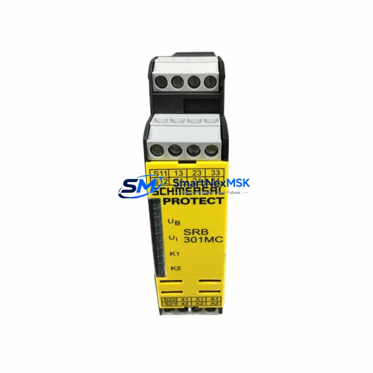
A successful SRB301MC retrofit begins well before the module arrives on site. Start by auditing the existing control cabinet: confirm the 24 VDC power supply rail — typically a SCHMERSAL SVS24 or a Phoenix Contact QUINT series unit — can sustain the inrush and steady-state current demand of the new relay alongside any co-located modules. Review the terminal block layout; the SRB301MC uses the same A1, A2, S11, S12, S21, S22, 13/14, 23/24, 33/34, and 41/42 terminal designations as the legacy SRB301, so existing ferrule-terminated wiring can usually be transferred directly.
If the original installation included a SCHMERSAL SRB201 (single-channel predecessor), the upgrade to SRB301MC requires adding a second input channel — plan for additional terminal space and a short wiring run from the second E-stop contact or safety door switch. Where the safety circuit feeds a SCHMERSAL AES series safety controller or a third-party safety PLC, verify that the output contact mapping in the controller’s I/O configuration matches the new relay’s contact numbering before energizing.
For lines that incorporate SCHMERSAL BNS series position switches or RSS series coded safety switches, the SRB301MC accepts their dry-contact outputs directly without additional signal conditioning. If the guarding system uses SCHMERSAL SLC240 or SLC440 safety light curtains with OSSD outputs, connect OSSD1 and OSSD2 to the S11/S21 and S12/S22 inputs respectively, and confirm the OSSD test pulse width is within the SRB301MC’s filter tolerance. Systems using SCHMERSAL MZM series solenoid interlocks or BDF series door switches can be wired directly to the dual-channel inputs without modification.
Where the retrofit involves a broader control platform migration — for example, moving from a legacy relay-logic panel to a Siemens S7-1500 safety CPU with a SIMATIC ET 200SP fail-safe I/O rack — the SRB301MC can serve as an interim hardwired safety layer while the new PLC program is validated. This staged approach allows the mechanical guarding and E-stop circuits to remain operational under the proven relay logic while the new software safety functions are tested offline. Programming cables and TIA Portal project files for the PLC side are unaffected by the relay swap.
Backplane and rack considerations are minimal for the SRB301MC since it is a standalone DIN-rail device, but if the cabinet also houses a SCHMERSAL Protect-IE gateway or an AS-Interface safety monitor such as the SCHMERSAL ASM series, confirm that the monitor’s input assignment table is updated to reflect any address changes introduced during the retrofit. Document all wiring changes in the circuit diagram before closing the cabinet.
Downtime Control During System Migration
Minimizing production downtime during a safety relay replacement requires a structured swap procedure. Before de-energizing the circuit, photograph or scan the existing terminal wiring and record all LED status indicators on the outgoing module. Power down only the affected safety zone — not the entire machine — by using the zone isolation switches or the relevant safety PLC output disable function if the controller supports partial shutdown.
Remove the old relay, install the SRB301MC on the DIN rail, and reconnect terminals in sequence using the documented wiring record. The SRB301MC’s LED array provides immediate feedback: a steady green power LED and flashing channel LEDs during the function test confirm correct wiring before the output contacts are enabled. Perform a full channel cross-fault test by deliberately opening each input channel independently and verifying that the safety outputs de-energize as expected.
Once the function test passes, restore power to the safety zone and execute a controlled machine restart under supervision. The original PLC program logic — including any safety function blocks referencing the relay’s feedback contact (Y1/Y2 monitoring loop) — requires no modification provided the contact numbering is preserved. If the machine uses a SCHMERSAL PSC1 safety controller or a Pilz PNOZ series relay in an adjacent zone, those devices remain unaffected and continue to hold their zones active during the swap, further limiting the footprint of the outage. Total planned downtime for a single-relay swap following this procedure is typically under 45 minutes for a prepared technician.
Retrofit Support FAQ
Q1: Is the SRB301MC a direct drop-in replacement for the SRB301 and SRB201?
The SRB301MC is electrically and mechanically compatible with the SRB301 series and can replace the SRB201 with the addition of a second input channel. Terminal designations, DIN rail footprint, and output contact ratings are identical to the SRB301, making it the recommended replacement for both discontinued variants.
Q2: What wiring changes are needed when replacing an OSSD-connected predecessor?
No additional wiring changes are required if the predecessor was already wired for dual-channel OSSD input. Connect OSSD1 to S11/S21 and OSSD2 to S12/S22. Confirm the OSSD test pulse suppression time in the light curtain or safety scanner settings matches the SRB301MC’s input filter specification before commissioning.
Q3: Does the unit ship with a functional test report, and what does the 12-month warranty cover?
Yes. Each SRB301MC is bench-tested prior to dispatch and ships with a functional test record confirming input channel response, output contact operation, and cross-fault detection. The 12-month warranty covers manufacturing defects and functional failures under normal operating conditions. It does not cover damage from incorrect wiring, overvoltage, or unauthorized modification.
Q4: Can the SRB301MC be used in a system that also includes AS-Interface safety modules?
Yes. The SRB301MC operates as a standalone hardwired device and can coexist in a cabinet with AS-Interface safety monitors such as the SCHMERSAL ASM series. The relay’s output contacts can feed the AS-Interface monitor’s safe input or directly control contactor coils, depending on the system architecture. No configuration changes to the AS-Interface network are required for the relay swap itself.
© 2026 SMARTNEXMSK. All rights reserved.
Original Source: https://smartnexmsk.com
Contact: sales@smartnexmsk.com | +86 18259474341