Schneider TRICONEX 2551 Retrofit-Ready Termination Panel for Tricon TMR Control Systems
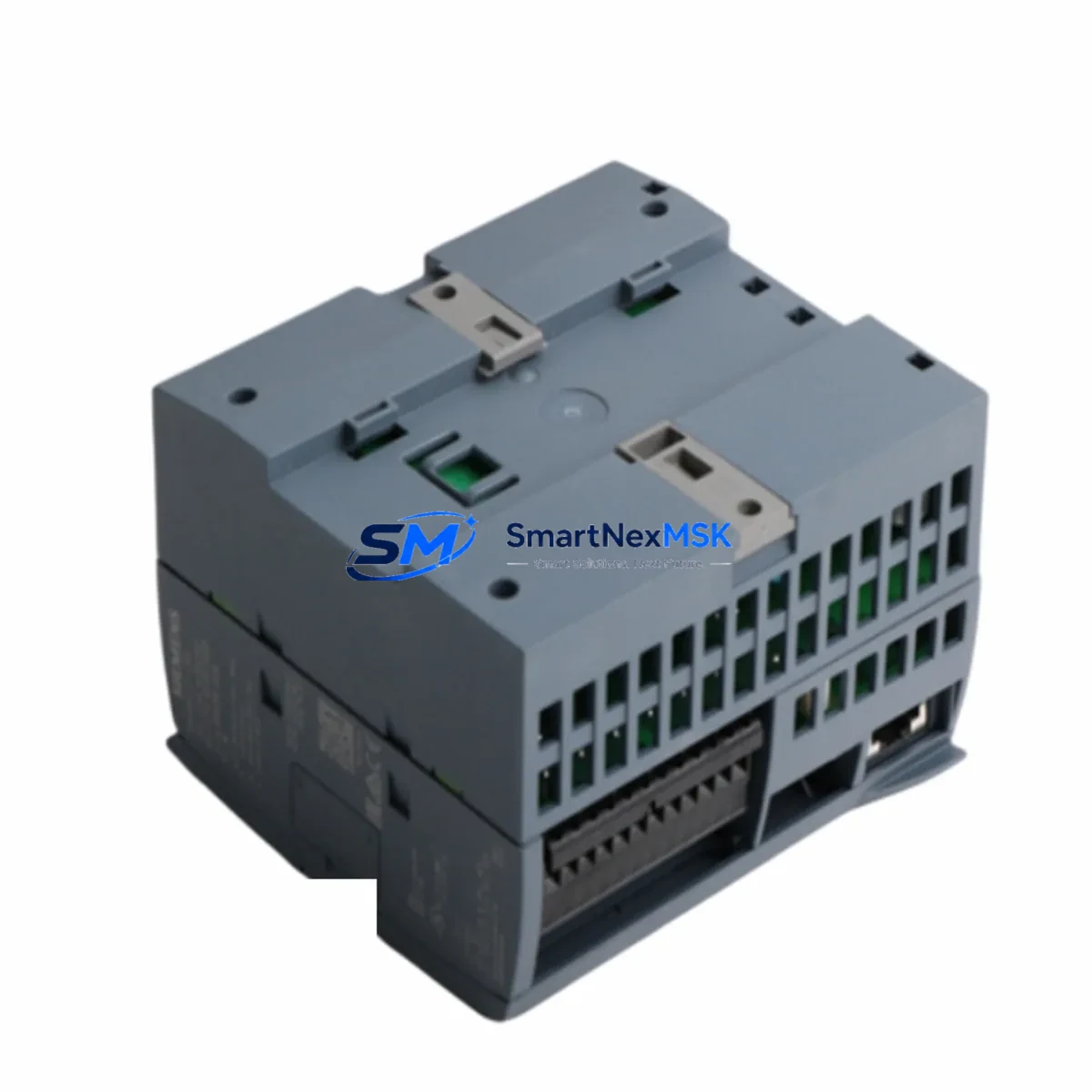
The TRICONEX 2551 is a safety-rated termination panel engineered for seamless integration into Tricon Triple Modular Redundant (TMR) safety systems. Designed by Schneider Electric under the TRICONEX brand, this module serves as a critical field-wiring interface between process instrumentation and the Tricon controller chassis. Whether you are executing a planned safety system upgrade, replacing an end-of-life component in an aging control cabinet, or restoring a production line after an unplanned shutdown, the TRICONEX 2551 provides the wiring compatibility, signal integrity, and SIL-rated performance your application demands.
Industrial facilities operating legacy Tricon systems — including those built around the Tricon v9 and Tricon v10 controller platforms — frequently encounter obsolescence challenges with original termination assemblies. The TRICONEX 2551 addresses this directly: it maintains the same terminal block layout, backplane connector footprint, and field-wiring scheme as the original factory configuration, eliminating the need for panel rewiring or cable rerouting during replacement. This compatibility is especially valuable in SIL 2 and SIL 3 certified loops where any modification to field wiring must be formally documented and re-validated.
When planning a retrofit around the TRICONEX 2551, engineers should verify several key parameters before committing to installation. Power supply capacity within the Tricon chassis must be confirmed against the aggregate draw of all installed I/O modules; the Tricon Power Supply Module (PSM) — typically a redundant pair — should be audited for available headroom. Backplane slot assignment and module addressing must be cross-referenced against the existing Tricon Main Chassis or Tricon Expansion Chassis configuration to ensure the replacement panel is recognized correctly by the controller without requiring a full program download.
Terminal wiring compatibility is another critical checkpoint. Field cables connected to the original termination panel must be mapped against the TRICONEX 2551 terminal numbering to confirm signal-to-channel alignment. In installations where the original panel was paired with a TRICONEX 2553 or TRICONEX 2554 termination assembly, the interconnecting cable harness and ribbon connector should be inspected for wear before reuse. If the system uses TRICONEX 3700A or TRICONEX 3721 I/O modules on the same chassis, their addressing scheme must remain undisturbed during the panel swap to avoid I/O map conflicts in the running safety application.
Program compatibility is a non-negotiable requirement in any Tricon retrofit. The safety application compiled in TriStation 1131 — Schneider Electric’s IEC 61131-3 compliant programming environment — must be reviewed to confirm that the I/O variable assignments, function block configurations, and cause-and-effect matrix entries associated with the replaced termination panel remain valid after the swap. In most cases, a like-for-like replacement of the TRICONEX 2551 does not require program modification, but a formal Management of Change (MOC) review is recommended per IEC 61511 requirements.
HMI integration should also be verified. Operator stations running Wonderware InTouch, Ignition SCADA, or OEM HMI panels connected to the Tricon system via Modbus TCP, OPC DA, or OPC UA communication links should be tested post-replacement to confirm that all process variable tags, alarm setpoints, and interlock status displays continue to reflect accurate field data. Communication links through the Tricon Communication Module (TCM) — including peer-to-peer links to other Tricon or Trident controllers — should be monitored during the first operational cycle after installation.
Upgrade Compatibility Table
| Parameter | Details |
|---|---|
| Compatible Platform | Tricon TMR Safety System (v9, v10, v11) |
| Backplane Interface | Tricon Main Chassis / Expansion Chassis backplane connector |
| Terminal Wiring | Field-wiring compatible with original TRICONEX 2551 terminal layout |
| Communication Compatibility | Modbus TCP, OPC DA/UA via Tricon Communication Module (TCM) |
| Safety Rating | SIL 2 / SIL 3 capable (per IEC 61508 / IEC 61511) |
| Installation Requirement | No panel rewiring required for like-for-like replacement |
| Programming Tool | TriStation 1131 (IEC 61131-3); no program modification typically required |
| Replacement Recommendation | Direct drop-in for end-of-life or damaged TRICONEX 2551 units |
| Commissioning Note | Verify module address, I/O map, and HMI tag integrity post-installation |
| Warranty | 12-Month Warranty included with every unit |
Retrofit Planning for Existing Automation Systems
A successful Tricon retrofit begins well before the maintenance window opens. The first step is a full audit of the existing control cabinet: document every module installed in the Tricon Main Chassis, including the Tricon Main Processor (MP), all I/O modules such as the TRICONEX 3703E digital input module and TRICONEX 3805E analog input module, and the redundant Tricon Power Supply Modules. This inventory establishes the baseline configuration against which the replacement TRICONEX 2551 will be validated.
Next, review the field termination architecture. In many legacy installations, the TRICONEX 2551 termination panel is connected to field instruments — pressure transmitters, temperature elements, solenoid valves, and discrete limit switches — through a structured cable harness. Each cable must be labeled and its terminal assignment recorded before disconnection. If the existing harness uses a TRICONEX 2551-to-chassis ribbon cable, inspect the connector pins for corrosion or mechanical damage and replace the cable if any degradation is found.
For facilities migrating from older Tricon v9 hardware to a v10 or v11 chassis, the TRICONEX 2551 termination panel is often retained as part of a phased upgrade strategy: the chassis and processor are replaced first, while the field termination panels — including the 2551 — remain in place to preserve field wiring continuity. This approach minimizes the scope of field work and reduces the risk of wiring errors during the migration. The Tricon Expansion Chassis and associated TRICONEX 2551 panels can typically be reused across chassis generations, provided the backplane interface revision is compatible.
Communication infrastructure should also be reviewed during retrofit planning. If the system uses a Tricon Communication Module (TCM 4351A) or TCM 4352A for Ethernet-based supervisory communication, confirm that the IP addressing scheme and network segmentation remain intact after the chassis work. Peer-to-peer safety links between Tricon controllers — often used in large process units with multiple safety instrumented functions — must be re-verified after any hardware change. Programming cables such as the TRICONEX 4351A serial interface or USB-to-serial adapters used with TriStation 1131 should be on hand during commissioning to support online diagnostics and program verification.
Downtime Control During System Migration
Minimizing unplanned downtime is the primary operational concern in any safety system retrofit. For the TRICONEX 2551 replacement, the recommended approach is a hot-standby swap procedure executed during a planned maintenance window, with the process unit placed in a safe state and all associated safety instrumented functions (SIFs) bypassed in accordance with the site’s bypass management procedure.
Before the maintenance window begins, prepare a complete pre-swap checklist: confirm the replacement TRICONEX 2551 has passed outgoing inspection and functional test at the supplier’s facility, verify that the unit’s revision level matches the installed base, and ensure that a backup copy of the TriStation 1131 project file — including all I/O configurations, cause-and-effect logic, and communication settings — has been archived to a secure location. This backup is the single most important safeguard against extended downtime in the event of an unexpected complication during the swap.
During the swap, follow a structured sequence: de-energize the field wiring circuits associated with the TRICONEX 2551, disconnect the terminal block wiring in labeled groups, remove the original panel, install the replacement unit, reconnect field wiring in reverse order, and re-energize. After power-up, use the TriStation 1131 online diagnostics to confirm that all I/O channels are reporting correctly and that no fault codes are active on the Tricon Main Processor. Verify HMI tag values against field instrument readings before releasing the process unit from bypass.
For facilities that cannot tolerate any interruption to safety coverage, a parallel installation strategy may be appropriate: install the replacement TRICONEX 2551 in an adjacent chassis slot, migrate field wiring one circuit at a time, and verify each channel before proceeding to the next. This approach extends the total migration time but eliminates the need for a full system bypass and allows the safety function to remain active throughout the process.
Retrofit Support FAQ
Q: Is the TRICONEX 2551 a direct drop-in replacement for the original unit without rewiring?
A: Yes. The TRICONEX 2551 maintains the same terminal block layout and backplane connector as the original factory configuration. In a like-for-like replacement scenario, no field rewiring is required. However, we recommend verifying terminal numbering against your as-built drawings before installation, as some early Tricon v9 installations used site-specific wiring modifications that may not match the standard layout.
Q: Does replacing the TRICONEX 2551 require a TriStation 1131 program download?
A: In most cases, no. A like-for-like termination panel replacement does not alter the I/O map or program logic, so a full download is not required. However, an online comparison between the installed program and the archived project file is strongly recommended post-installation to confirm configuration integrity. If the replacement unit has a different hardware revision, consult the Tricon compatibility matrix before proceeding.
Q: What commissioning checks should be performed after installing the replacement panel?
A: After installation, perform the following checks in sequence: (1) confirm all I/O channels are active and fault-free in TriStation 1131 online diagnostics; (2) verify field instrument readings match HMI tag values for all channels associated with the TRICONEX 2551; (3) test each safety instrumented function (SIF) connected to the panel by simulating the trip condition and confirming the correct final element response; (4) document the completed checks in the site’s MOC record and close out the bypass in the bypass management system.
Q: What warranty coverage is included, and what does it cover?
A: Every TRICONEX 2551 unit supplied by SMARTNEXMSK includes a 12-month warranty covering manufacturing defects and functional failures under normal operating conditions. Each unit undergoes outgoing functional testing prior to shipment. Warranty claims are supported by our technical team; contact sales@smartnexmsk.com or +86 18259474341 for RMA processing and technical assistance.
© 2026 SMARTNEXMSK. All rights reserved.
Original Source: https://smartnexmsk.com
Contact: sales@smartnexmsk.com | +86 18259474341