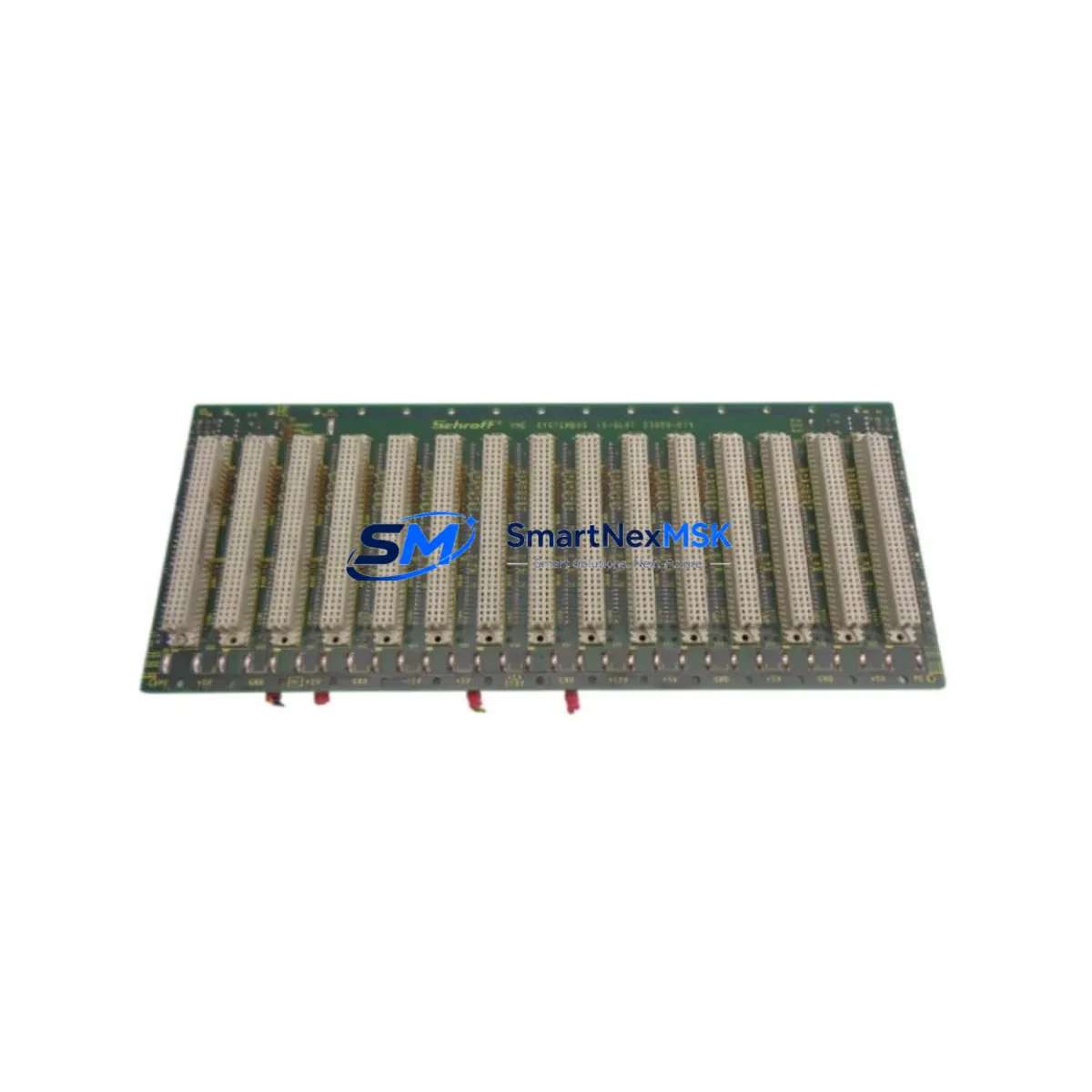
Schroff 23000-015 Maintenance-Ready Spare for 19-Inch Subrack Automation
The Schroff 23000-015 is an original nVent Schroff 19-Inch Subrack backplane board engineered for continuous industrial operation. Designed to IEC 60297 mechanical standards, this component serves as a critical structural and electrical backbone within modular control enclosures across process automation, power distribution, and industrial computing environments. For maintenance engineers managing aging control systems or executing planned overhauls, having a verified original spare of the 23000-015 on hand is a fundamental risk-reduction strategy — one that directly shortens mean time to repair (MTTR) and protects production uptime.
Whether you are responding to an unplanned subrack failure, executing a scheduled cabinet refurbishment, or building a strategic spare parts inventory for a multi-site facility, the Schroff 23000-015 delivers the dimensional accuracy, connector alignment, and material quality required for drop-in replacement without system reconfiguration. Each unit shipped by SMARTNEXMSK is pre-tested, individually inspected, and covered by a 12-month warranty from the date of delivery.
Spare Maintenance Table
| Parameter | Specification |
|---|---|
| Part Number / SKU | 23000-015 |
| Brand | Schroff (nVent) |
| Series | 19-Inch Subrack / IEC 60297 |
| Product Type | Industrial Subrack Backplane |
| Mechanical Standard | IEC 60297-3 / DIN 41494 |
| Form Factor | 19-Inch (482.6 mm) Rack-Mount |
| Country of Origin | Germany |
| Operating Temperature | 0°C to +55°C (typical industrial range) |
| Storage Temperature | -25°C to +70°C |
| Compatibility | IEC 60297-compliant 19-Inch subrack enclosures; nVent Schroff modular rack systems |
| Installation | Direct slide-in replacement; no modification required for compatible enclosures |
| Application Environment | Process automation, industrial computing, power distribution, control cabinet |
| Maintenance Recommendation | Inspect connector pins and card guides annually; replace on visible mechanical wear or intermittent contact faults |
| Condition | Original, new, pre-tested |
| Warranty | 12 Months from date of delivery |
Maintenance Planning for Continuous Operation
When a subrack backplane such as the Schroff 23000-015 is identified for replacement during a scheduled inspection or emergency fault response, experienced maintenance engineers know that the backplane itself is rarely the only component requiring attention. A thorough cabinet audit at the time of replacement significantly reduces the risk of repeat failures and secondary downtime events.
Begin by verifying the 24 VDC or 48 VDC power supply module feeding the subrack — degraded output voltage or excessive ripple is a common root cause of backplane connector stress and premature wear. Inspect the DIN rail terminal blocks and cable harness connectors routed to the subrack for signs of insulation fatigue, loose crimps, or oxidation at the contact points. If the subrack houses digital or analog I/O modules, verify that each module seats correctly in the replacement backplane and that signal integrity is confirmed before returning the system to service.
For systems incorporating communication modules — such as PROFIBUS DP, PROFINET, or Modbus RTU interface cards — confirm that the bus termination resistors and cable shielding remain intact after the backplane swap. In enclosures where signal isolators or galvanic separation modules are installed between field instruments and the control rack, these should be functionally tested post-replacement to ensure loop integrity. Check miniature circuit breakers (MCBs) and fuse holders within the same distribution zone for correct rating and contact condition.
If the subrack is part of a larger VMEbus, CompactPCI, or proprietary industrial backplane architecture, cross-reference the 23000-015 slot assignments against the system’s I/O map before powering up. Where HMI panels or operator terminals are connected via the same control cabinet, verify communication continuity after the replacement to avoid nuisance alarms or operator interface faults. Enclosures with fan tray assemblies or thermal management modules should also be inspected — a failed cooling unit is frequently the underlying cause of backplane thermal stress and connector degradation over time.
Building a structured spare parts kit around the Schroff 23000-015 — including a matched power supply, a set of I/O module spares, and a replacement fan tray — is a best practice for facilities operating critical automation infrastructure with long replacement lead times.
Site Replacement Workflow
Step 1 — Isolation and Lockout: De-energize the control cabinet following site LOTO procedures. Confirm zero-energy state at the subrack power input terminals before proceeding.
Step 2 — Module Extraction: Document the slot positions of all installed cards (I/O modules, communication cards, CPU boards) using photographs or a slot map. Extract each module in sequence, placing them in anti-static bags labeled by slot number.
Step 3 — Backplane Removal: Disconnect all rear-wired connectors and cable harnesses from the existing backplane. Remove the mounting hardware securing the subrack to the rack frame. Slide out the old 23000-015 unit.
Step 4 — Replacement Installation: Slide the new Schroff 23000-015 into the rack frame. Secure mounting hardware to the specified torque. Reconnect all rear-wired connectors in the documented sequence. Verify connector seating and cable routing before re-inserting modules.
Step 5 — Module Re-insertion and Verification: Re-insert each module into its original slot position. Confirm card guide alignment and front-panel locking. Restore power and verify system startup sequence, I/O status, and communication link indicators.
Step 6 — Functional Test: Execute a point-to-point I/O check against the system’s test procedure. Confirm HMI displays correct process values. Log the replacement in the site maintenance record with the new unit’s serial number and warranty start date.
This workflow is applicable whether replacing a failed unit under emergency conditions or executing a proactive swap during a planned maintenance window. The dimensional compatibility of the 23000-015 with IEC 60297-compliant enclosures ensures that no mechanical modification is required, minimizing replacement time and reducing the risk of installation errors.
Spare Parts Support FAQ
Q1: Is the Schroff 23000-015 supplied as a new original part or a refurbished unit?
All units supplied by SMARTNEXMSK are original new components sourced from authorized distribution channels. Each unit undergoes pre-shipment functional inspection and is covered by a 12-month warranty from the date of delivery. Refurbished or reconditioned units are never substituted without explicit customer agreement.
Q2: How do I confirm compatibility with my existing subrack enclosure before ordering?
The Schroff 23000-015 is designed to IEC 60297-3 / DIN 41494 mechanical standards and is compatible with standard 19-Inch subrack enclosures within the nVent Schroff modular rack system family. To confirm compatibility, provide your enclosure model number and current backplane part number to our technical team at sales@smartnexmsk.com. We will verify dimensional fit and connector alignment before shipment.
Q3: What is the typical lead time and how is the unit tested before shipping?
In-stock units are dispatched within 1–3 business days. Each 23000-015 is visually inspected for mechanical integrity, connector condition, and labeling accuracy prior to packaging. Units are shipped in anti-static protective packaging with a test report and warranty certificate. Express shipping options are available for emergency maintenance situations.
Q4: What spare parts inventory strategy is recommended for facilities running Schroff subrack-based systems?
For facilities with multiple 19-Inch subrack installations, maintaining at least one 23000-015 backplane spare per system type is recommended, alongside matched power supply modules and a set of the most critical I/O and communication cards. A documented spare parts list tied to each control cabinet’s bill of materials enables faster fault response and supports long-term system life extension beyond the original product’s active production period.
© 2026 SMARTNEXMSK. All rights reserved.
Original Source: https://smartnexmsk.com
Contact: sales@smartnexmsk.com | +86 18259474341