SCHUMACHER 1731-0049 Retrofit-Ready Pneumatic CPU Board for Legacy Control Systems
The SCHUMACHER 1731-0049 is a high-reliability pneumatic CPU board engineered for seamless integration into aging industrial control architectures. As a direct retrofit replacement for the 1730-7015 and cross-compatible with the 43H4A-2.33-072 and 853-126733-021 reference designations, this board addresses one of the most persistent challenges in industrial automation: maintaining operational continuity when original OEM components reach end-of-life or become unavailable through standard supply channels.
Manufactured in Germany to exacting industrial standards, the 1731-0049 is designed for environments where precision signal processing, pneumatic sequencing logic, and deterministic cycle control are non-negotiable. Whether you are managing a scheduled overhaul, responding to an unplanned board failure, or executing a phased modernization of a legacy pneumatic control cabinet, this CPU board provides the functional parity and physical compatibility required to restore full system operation with minimal engineering rework.
Upgrade Compatibility Table
| Parameter | Details |
|---|---|
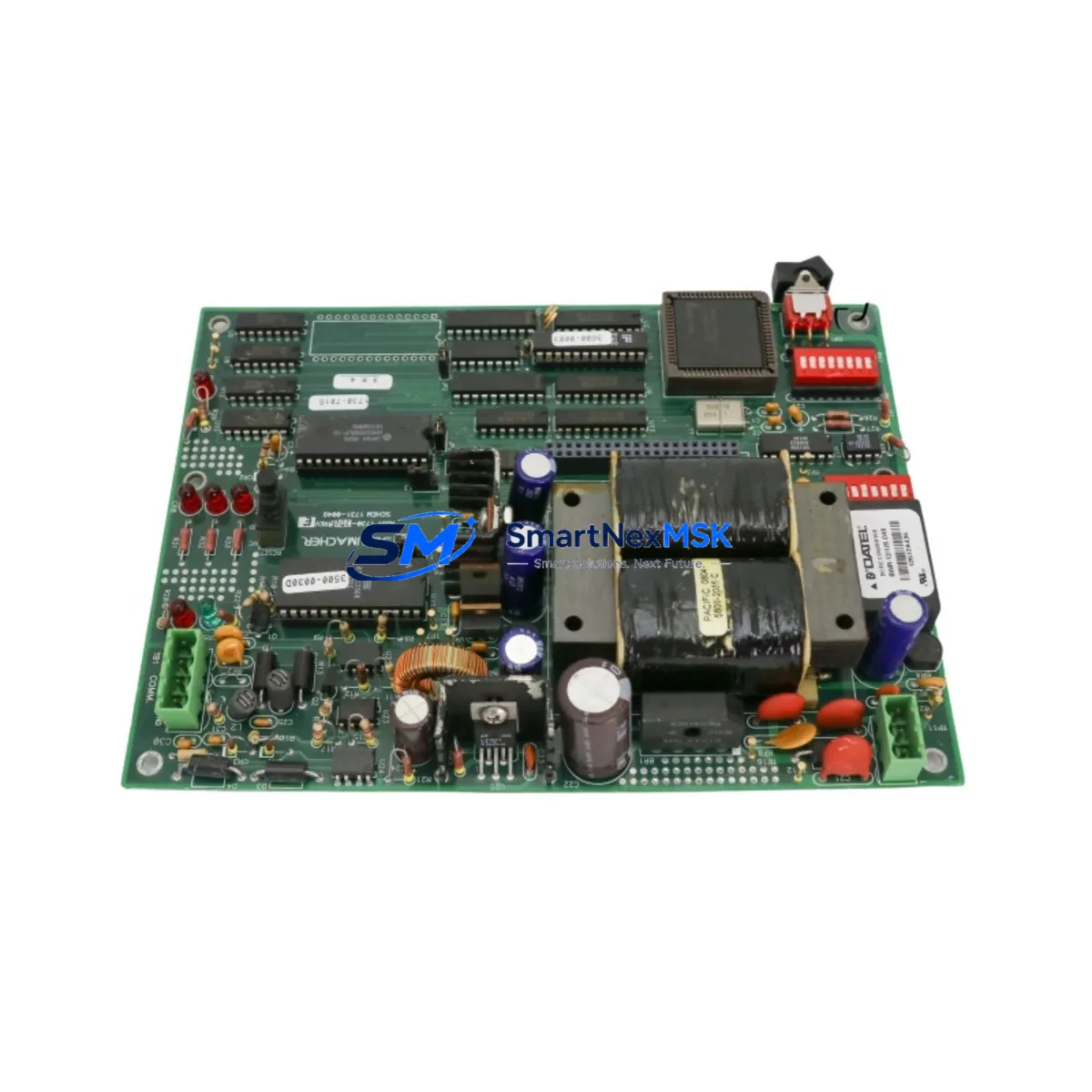
| Primary Part Number | SCHUMACHER 1731-0049 |
| Cross-Reference / Replacement For | 1730-7015 | 43H4A-2.33-072 | 853-126733-021 |
| Board Diameter / Form Factor | DIA 42.5 CM — verify rack slot clearance before installation |
| Processor Configuration | 1K-6Z2-265 designation; confirm firmware revision with existing backplane |
| Installation Interface | Direct backplane mount; verify connector pitch and pin-out against original board drawing |
| Communication Compatibility | Pneumatic sequencing bus; confirm signal voltage levels match existing I/O wiring |
| Replacement Recommendation | Suitable for like-for-like swap of 1730-7015; functional testing recommended post-installation |
| Commissioning Notes | Re-verify module address settings, terminal wiring polarity, and cycle timing parameters after board swap |
| Weight | 2,600 g — handle with ESD precautions |
| Country of Origin | Germany (DE) |
| Warranty | 12-Month Warranty — covers manufacturing defects under normal operating conditions |
Retrofit Planning for Existing Automation Systems
A successful retrofit of the SCHUMACHER 1731-0049 into an existing pneumatic control system requires methodical pre-installation planning. Before removing the failed or obsolete board, engineers should document the full rack configuration, including the positions of adjacent I/O expansion modules, terminal block wiring assignments, and any field bus adapters connected to the same backplane segment. In many legacy installations, the CPU board shares a common power rail with analog input cards and digital output modules, so verifying that the replacement board’s power draw does not exceed the rack’s available capacity is a critical first step.
When the control cabinet houses a mixed architecture — for example, a combination of pneumatic sequencing boards alongside discrete relay output modules and analog signal conditioners — the retrofit scope often extends beyond the CPU board itself. Technicians frequently find that the original wiring harness, designed for the 1730-7015 pinout, requires minor adaptation to match the 1731-0049 terminal layout. A side-by-side comparison of both boards’ wiring diagrams before disconnecting any field cables will prevent miswiring errors that could damage downstream actuators or sensors.
For systems that also incorporate a dedicated power supply module feeding the CPU rack, confirm that output voltage stability and ripple specifications remain within the replacement board’s input tolerance range. In older installations, power supply modules may themselves be approaching end-of-life, and a simultaneous replacement of both the CPU board and the rack power supply — using a compatible unit from the same control platform — is often the more cost-effective long-term strategy.
Communication continuity is another key consideration. If the existing system uses a serial communication link between the pneumatic CPU board and an upstream supervisory controller or HMI panel, the communication parameters — baud rate, parity, stop bits, and station address — must be re-entered or verified in the replacement board’s configuration registers before the system is returned to automatic mode. In installations where the HMI screen displays process values derived from the CPU board’s internal registers, a full HMI screen validation cycle should be completed to confirm that all data tags map correctly to the new board’s memory addresses.
Technicians working on systems that include a programming cable interface for on-site logic adjustments should also verify that the cable type and communication protocol used with the original 1730-7015 remain compatible with the 1731-0049. In some retrofit scenarios, an updated programming adapter or a revised software driver version may be required to establish a reliable connection. Having the correct programming cable and a laptop with the appropriate configuration software on-site before beginning the swap will significantly reduce unplanned downtime.
Where the control system includes a rack-mounted communications module handling fieldbus or point-to-point links to remote I/O stations, the module address assignments stored in the CPU board’s configuration table must be re-verified after the board swap. Address conflicts between the replacement CPU board and existing network nodes are a common source of post-retrofit communication faults that can be difficult to diagnose without a complete network topology map.
Downtime Control During System Migration
Minimizing production downtime during a CPU board replacement is achievable with disciplined pre-work. The most effective approach is to complete all preparatory steps — wiring documentation, configuration backup, spare parts staging, and test procedure preparation — during a scheduled maintenance window or during normal production hours, so that the physical board swap itself can be executed within a single planned shutdown period.
Before initiating the swap, back up the existing program logic and configuration data from the original board if the system’s architecture supports it. Even in older pneumatic control systems where full program upload is not possible, capturing a photographic record of all DIP switch settings, jumper positions, and terminal wiring connections provides a reliable reference for restoring the system to its pre-fault state. This documentation also serves as the baseline for the post-installation functional test, which should step through each pneumatic output sequence and verify that actuator response times and pressure setpoints remain within specification.
For critical production lines where even a brief interruption carries significant cost, consider staging a pre-tested and pre-configured 1731-0049 board in advance, so that the physical swap can be completed in the shortest possible time. Pre-testing the replacement board on a bench fixture that replicates the rack’s power supply and signal interface conditions allows the engineering team to confirm board functionality before the production system is taken offline. This approach also provides an opportunity to identify any firmware or configuration differences between the original and replacement boards before they become a problem on the production floor.
After the board is installed and the system is powered up, a structured commissioning sequence — starting with power supply verification, followed by communication link confirmation, I/O point-by-point testing, and finally a full automatic cycle run — ensures that all system functions are restored before the line is returned to production. Maintaining a detailed commissioning record for each retrofit provides traceability for future maintenance events and supports compliance with quality management requirements.
Retrofit Support FAQ
Q1: Is the SCHUMACHER 1731-0049 a direct drop-in replacement for the 1730-7015?
The 1731-0049 is cross-referenced as a functional replacement for the 1730-7015 and the 43H4A-2.33-072. While the core pneumatic CPU functions are equivalent, engineers should verify connector pinout, board dimensions (DIA 42.5 CM), and configuration register settings before installation. Minor wiring adaptations may be required depending on the specific cabinet layout.
Q2: What commissioning steps are required after installing the 1731-0049?
After physical installation, re-verify module address settings, terminal wiring polarity, communication parameters (baud rate, station address), and cycle timing values. Perform a full I/O point test and a complete automatic cycle run before returning the system to production. HMI data tag mapping should also be validated if the board interfaces with an operator panel.
Q3: How is the board tested before shipment?
Each SCHUMACHER 1731-0049 unit is subject to pre-shipment functional testing covering power-on self-test, signal I/O verification, and communication interface checks. Units are shipped with ESD-protective packaging. The 12-month warranty covers manufacturing defects under normal operating conditions from the date of delivery.
Q4: What is the lead time and warranty coverage?
The 1731-0049 is available from in-stock inventory for immediate dispatch. Standard lead time is subject to current stock levels — contact our sales team for real-time availability confirmation. All units are covered by a 12-month warranty against manufacturing defects. Warranty claims are supported by our technical team with replacement or repair options.
© 2026 SMARTNEXMSK. All rights reserved.
Original Source: https://smartnexmsk.com
Contact: sales@smartnexmsk.com | +86 18259474341