SCS UFS-22 Maintenance-Ready Spare for UFS Series Automation
Unplanned downtime in drive-controlled deceleration circuits is one of the most disruptive failure modes in industrial automation. The SCS UFS-22 braking unit is a critical component in UFS Series variable frequency drive (VFD) systems, responsible for dissipating regenerative energy during motor deceleration. When this unit fails, the entire drive system may fault, triggering emergency stops and halting production lines. Maintaining a verified spare of the UFS-22 in your site inventory is a proven strategy for minimizing mean time to repair (MTTR) and protecting operational continuity.
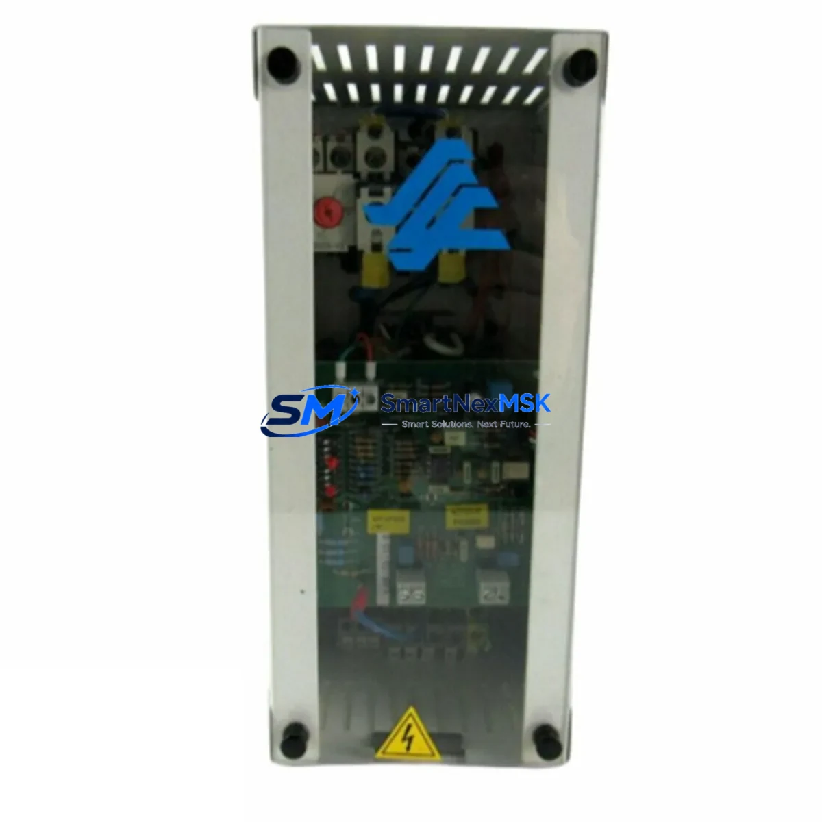
This listing supplies an original SCS UFS-22 braking unit, sourced through authorized industrial channels, pre-tested before dispatch, and backed by a 12-month warranty. It is intended for maintenance engineers and procurement teams managing UFS Series drive systems in manufacturing, process control, material handling, and heavy-duty automation environments.
Spare Maintenance Table
| Parameter | Specification / Value |
|---|---|
| Part Number / SKU | UFS-22 |
| Brand | SCS |
| Product Type | Braking Unit |
| Compatible Series | UFS Series VFD / Drive Systems |
| Function | Regenerative braking energy dissipation during motor deceleration |
| Origin | China (CN) |
| Installation | Panel-mount / DIN rail compatible (verify with UFS Series drive documentation) |
| Application Environment | Industrial automation, process control, material handling, HVAC drive systems |
| Compatibility Verification | Match drive model, voltage class, and braking resistor rating before installation |
| Maintenance Recommendation | Inspect braking resistor, wiring terminals, and thermal dissipation path during each planned maintenance cycle |
| Pre-shipment Testing | Functional test performed before dispatch |
| Warranty | 12 Months |
| Lead Time | In-stock units ship within 1–3 business days |
Maintenance Planning for Continuous Operation
When a UFS-22 braking unit is flagged for replacement during a planned inspection or emergency fault response, experienced maintenance engineers know that the braking unit rarely fails in isolation. A systematic review of the surrounding electrical circuit is essential to prevent repeat failures and ensure the drive system returns to full operational status.
Begin by inspecting the braking resistor connected to the UFS-22 — thermal stress from repeated deceleration cycles can degrade resistor elements, and a failed resistor will immediately stress a newly installed braking unit. Check the DC bus capacitors within the associated VFD for signs of bulging or electrolyte leakage, as elevated DC bus voltage is a common root cause of braking unit failure. Review the main power input terminals and AC line fuses for signs of overheating or loose connections that may have contributed to abnormal voltage spikes.
On the control side, verify the integrity of the drive control board and its braking chopper gate drive signal. A faulty gate drive output can destroy a replacement braking unit within minutes of commissioning. If the UFS Series drive communicates via RS-485 or PROFIBUS communication modules, confirm that the communication link is stable and that no fault codes related to braking overcurrent or overvoltage are latched in the drive’s fault history log.
For systems with I/O expansion modules monitoring motor speed feedback or encoder signals, validate that speed reference signals are within normal range — erratic speed commands can cause excessive regenerative energy that overloads the braking circuit. Where signal isolators are used between the PLC and the drive’s analog input, check isolation integrity to rule out ground loop interference affecting the speed reference.
In control cabinet inspections, also examine the 24VDC power supply module feeding the drive’s control logic, the terminal blocks and wiring ferrules on the braking resistor circuit, and any thermal overload relays or circuit breakers in the motor branch circuit. For older UFS Series installations, consider proactively replacing the drive cooling fan if it has exceeded its rated service hours — inadequate airflow is a leading cause of thermal stress on braking components. Finally, if an HMI panel is used for drive parameter monitoring, use it to review the braking usage ratio parameter and confirm it remains within the drive manufacturer’s recommended threshold after the UFS-22 replacement.
Site Replacement Workflow
Replacing the SCS UFS-22 in a live industrial environment requires a structured approach to minimize downtime and avoid secondary damage to the drive system.
Step 1 — Isolation and Lockout/Tagout: De-energize the drive system and verify that the DC bus has fully discharged before opening the control cabinet. DC bus voltage can remain hazardous for several minutes after power removal.
Step 2 — Documentation: Photograph the existing wiring connections to the braking unit terminals (typically labeled B1/B2 or P/PB depending on the drive model) before disconnecting any cables. Record the drive’s current parameter settings if accessible.
Step 3 — Component Removal: Disconnect the braking resistor leads and any control signal wiring from the UFS-22. Remove the unit from its mounting position, noting any thermal interface material or mounting hardware that must be reused or replaced.
Step 4 — Compatibility Confirmation: Before installing the replacement UFS-22, confirm that the voltage class, current rating, and physical form factor match the original unit and the UFS Series drive model in service. Cross-reference the drive’s technical manual if available.
Step 5 — Installation and Wiring: Mount the new UFS-22, reconnect all terminals per the documented wiring layout, and verify torque specifications on terminal screws to prevent loose connections under vibration.
Step 6 — Commissioning Test: Re-energize the system and perform a controlled deceleration test at reduced load to confirm the braking unit is operating correctly before returning the system to full production duty. Monitor the drive’s braking usage ratio parameter during the test.
This workflow supports rapid, safe replacement that restores system compatibility, reduces total downtime, and maintains the integrity of the UFS Series drive installation for long-term operation.
Spare Parts Support FAQ
Q1: What is the warranty coverage for the SCS UFS-22 supplied through this listing?
All UFS-22 units supplied through this listing are covered by a 12-month warranty from the date of shipment. Coverage includes manufacturing defects and functional failures under normal operating conditions. Units are pre-tested before dispatch to verify operational integrity.
Q2: How do I confirm compatibility between the UFS-22 and my existing UFS Series drive installation?
Compatibility should be verified against the drive model number, voltage class (e.g., 380V or 480V), and the rated braking current of the original unit. Refer to the SCS UFS Series drive technical manual or contact our technical team with your drive model number for confirmation before ordering.
Q3: Can the UFS-22 be used as a direct replacement for aging or discontinued braking units in legacy UFS Series systems?
Yes. The UFS-22 is suitable for life-extension programs on older UFS Series installations where the original braking unit has reached end of service life. Ensure that the braking resistor and associated wiring are also inspected and replaced if necessary to prevent premature failure of the new unit.
Q4: What pre-shipment checks are performed on each UFS-22 unit?
Each unit undergoes functional testing prior to dispatch to verify switching performance and terminal integrity. Units are packaged with anti-static protection and impact-resistant materials to ensure safe arrival. Inspection records are available upon request for quality-critical procurement processes.
© 2026 SMARTNEXMSK. All rights reserved.
Original Source: https://smartnexmsk.com
Contact: sales@smartnexmsk.com | +86 18259474341