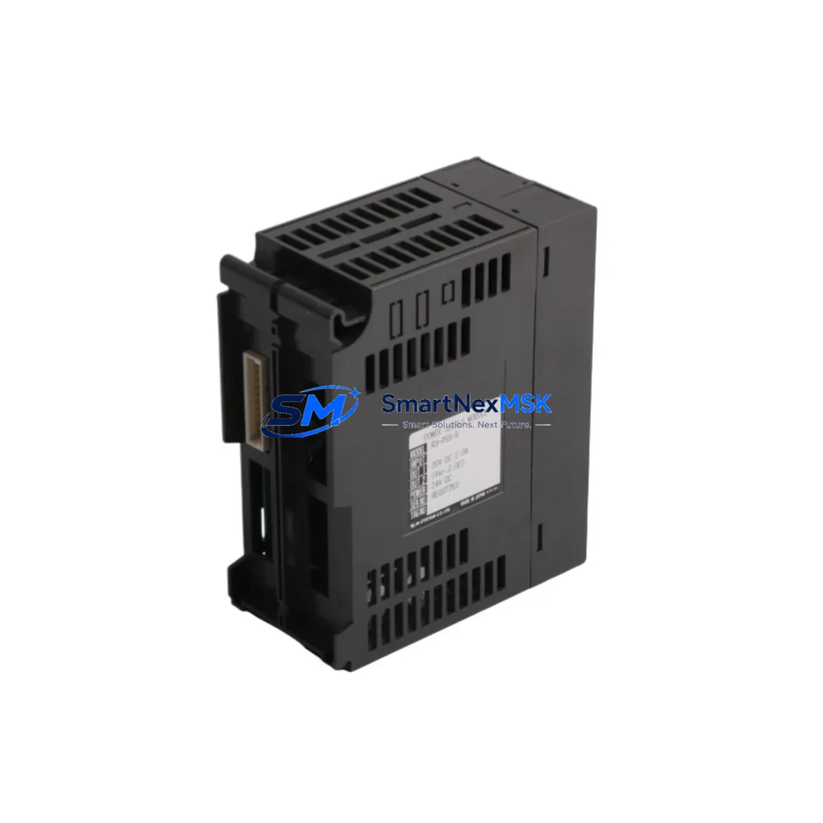
Servo R3-PS3-R Retrofit Power Supply for PS3 Series Control Systems: Compatible Modernization & Smooth System Upgrade
The Servo R3-PS3-R is a retrofit-ready power supply module engineered for seamless integration into Servo PS3 Series PLC control systems. As legacy automation infrastructure ages and original power supply modules reach end-of-life, the R3-PS3-R provides a reliable, drop-in replacement path that preserves existing wiring configurations, backplane interfaces, and program logic — minimizing engineering rework and unplanned downtime during system modernization projects.
Industrial facilities operating aging PS3 Series control cabinets frequently encounter discontinued OEM power modules, degraded output regulation, and increasing mean-time-between-failure rates. The R3-PS3-R addresses these challenges directly: it maintains full electrical compatibility with the PS3 backplane bus, supports the same terminal block wiring layout as the original module, and delivers stable DC output to power I/O expansion racks, communication modules, and CPU units without requiring firmware changes or hardware reconfiguration.
For engineers managing multi-rack PS3 installations, the R3-PS3-R integrates cleanly alongside existing components such as the Servo R3-NC1 motion control module, R3-DA16 analog output module, R3-XA8 I/O expansion unit, and R3-COM communication interface. When upgrading a control cabinet that also houses a Servo PS3-CPU module and PS3-series HMI panel, the R3-PS3-R ensures the power budget remains within specification across all installed modules — a critical verification step before commissioning any retrofit.
Upgrade Compatibility Table
| Parameter | Details |
|---|---|
| Model | Servo R3-PS3-R |
| Compatible Series | Servo PS3 Series PLC |
| Replaces | Original Servo PS3 power supply modules (discontinued) |
| Backplane Interface | PS3-series backplane bus — direct plug-in, no adapter required |
| Terminal Wiring | Identical terminal layout to OEM module; no rewiring required |
| Communication Compatibility | Compatible with RS-232, RS-485, and Ethernet-based PS3 communication modules |
| Installation Requirement | Standard DIN rail or rack mount; fits existing PS3 chassis slot |
| Replacement Recommendation | Direct 1:1 replacement; verify total rack power load before installation |
| Commissioning Notes | Confirm module address settings; validate I/O scan cycle after power-up |
| Warranty | 12-Month Warranty — covers manufacturing defects and functional failure |
Retrofit Planning for Existing Automation Systems
A successful PS3 Series retrofit begins with a thorough audit of the existing control cabinet. Before removing the legacy power supply, engineers should document the current terminal wiring diagram, record module slot assignments, and verify the total power consumption of all installed modules. In a typical PS3 rack, this includes the PS3-CPU processor module, one or more R3-DA16 analog output modules, R3-XA8 digital I/O expansion units, and a R3-COM Ethernet communication module. The R3-PS3-R must be confirmed capable of supplying sufficient current to all downstream modules before the retrofit proceeds.
Terminal block compatibility is a key checkpoint. The R3-PS3-R uses the same screw-terminal layout as the original PS3 power module, which means existing field wiring — including AC input lines, DC output distribution, and protective earth connections — can be transferred directly without modification. This significantly reduces the risk of wiring errors during the changeover window.
For facilities that have integrated Servo PS3-series HMI panels or third-party SCADA systems via Modbus RTU or Modbus TCP over the R3-COM communication interface, the power supply replacement does not affect communication protocol configuration. HMI screen tags, PLC variable addresses, and communication link parameters remain unchanged after the R3-PS3-R is installed, provided the CPU module retains its program memory during the swap — which is standard behavior when battery-backed RAM is present in the PS3-CPU module.
Where I/O expansion is planned as part of the broader upgrade, the R3-PS3-R’s power headroom supports the addition of supplementary R3-XA8 I/O expansion racks or R3-NC1 motion control modules without requiring a secondary power supply in most standard configurations. Always calculate the aggregate module current draw against the R3-PS3-R rated output before finalizing the expansion design.
Programming cable compatibility should also be confirmed during retrofit planning. The Servo PS3 programming cable (USB or RS-232 type, depending on CPU variant) connects to the CPU module independently of the power supply slot, so program upload, verification, and online monitoring can proceed immediately after the R3-PS3-R is energized.
Downtime Control During System Migration
Minimizing production downtime is the primary operational constraint in any live-system power supply replacement. The recommended approach for R3-PS3-R installation follows a structured cold-swap procedure: schedule the replacement during a planned maintenance window, perform a full program backup from the PS3-CPU module to a laptop or memory card before de-energizing the rack, and photograph the existing terminal wiring before disconnection.
Once the legacy power module is removed and the R3-PS3-R is seated in the chassis slot, reconnect AC input and DC output terminals per the documented wiring diagram. Power up the rack and verify that the CPU module enters RUN mode, all I/O modules report healthy status on the diagnostic LEDs, and communication links to the R3-COM Ethernet module and any connected HMI panels are re-established within the expected timeout period.
For critical processes where even a brief interruption is unacceptable, a parallel hot-standby configuration using a secondary PS3 rack can be pre-staged and switched over at the network level, with the R3-PS3-R installed in the standby rack during normal operation. This approach preserves full control continuity and allows the primary rack to be serviced without affecting the production process.
All R3-PS3-R units supplied by SMARTNEXMSK undergo pre-shipment functional testing, including output voltage verification, load regulation testing, and backplane interface continuity checks. Units are shipped with a test report and are covered by a 12-month warranty against manufacturing defects and functional failure from the date of delivery.
Retrofit Support FAQ
Q1: Is the Servo R3-PS3-R a direct replacement for the original PS3 Series power supply module?
Yes. The R3-PS3-R is designed as a 1:1 replacement for the original Servo PS3 Series power supply. It uses the same backplane connector, identical terminal block layout, and equivalent DC output specifications. No hardware adapters, wiring modifications, or firmware changes are required for a standard replacement installation.
Q2: Will replacing the power supply affect the PLC program or HMI configuration?
No. The R3-PS3-R replacement does not affect program memory stored in the PS3-CPU module, provided the CPU’s battery-backed RAM is functional. HMI screen configurations, Modbus communication parameters, and I/O variable mappings remain intact. A program backup is recommended as a precautionary measure before any hardware swap.
Q3: What wiring checks should be performed before commissioning the R3-PS3-R?
Verify AC input voltage matches the module’s rated input range, confirm protective earth continuity, and check that DC output terminal connections are secure and correctly polarized. Measure no-load output voltage before connecting the backplane load. Confirm total module current draw does not exceed the R3-PS3-R rated output capacity, particularly if I/O expansion modules or communication modules are installed in the same rack.
Q4: What does the 12-month warranty cover, and how is it claimed?
The 12-month warranty covers manufacturing defects and functional failure under normal operating conditions. It does not cover damage caused by incorrect installation, overvoltage, or physical mishandling. To initiate a warranty claim, contact SMARTNEXMSK with the order reference, a description of the fault, and the pre-shipment test report supplied with the unit. Replacement or repair will be arranged within the warranty period.
© 2026 SMARTNEXMSK. All rights reserved.
Original Source: https://smartnexmsk.com
Contact: sales@smartnexmsk.com | +86 18259474341