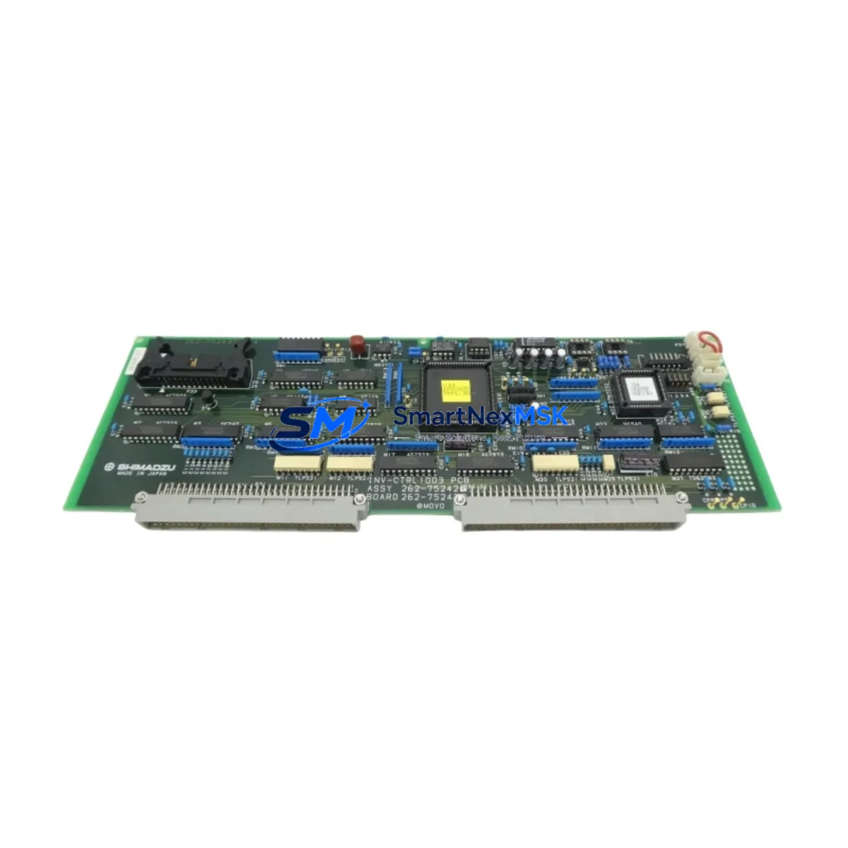
SHIMADZU INV-CTRL 1003 262-75242B Maintenance-Ready Spare MFS460
When an MFS460-series variable frequency drive trips offline on a critical production line, every minute of unplanned downtime translates directly into lost output and escalating recovery costs. The SHIMADZU INV-CTRL 1003 262-75242B (also cross-referenced as MFS460-042, MEI T001-0029, and 0190-24445) is an original inverter control PCB board engineered for the MFS460 drive platform. Sourced from verified supply channels, each unit is function-tested before dispatch and backed by a 12-month warranty, giving maintenance engineers and procurement teams the confidence to stock this board as a first-line spare rather than a last-resort emergency order.
Industrial facilities running SHIMADZU MFS460 drives in pump, fan, compressor, or conveyor applications understand that the control board is the nerve centre of the inverter. Gate-drive signals, DC-bus monitoring, fault-detection logic, and communication handshaking all pass through this assembly. A degraded or failed INV-CTRL 1003 board typically manifests as persistent overcurrent faults, erratic speed reference tracking, loss of keypad or fieldbus communication, or a drive that powers up but refuses to run. Stocking a verified replacement eliminates the diagnostic ambiguity and compresses mean-time-to-repair from days to hours.
Spare Maintenance Table
| Parameter | Detail |
|---|---|
| Part Number | INV-CTRL 1003 / 262-75242B |
| Cross Reference | MFS460-042 | MEI T001-0029 | 0190-24445 |
| Compatible Series | SHIMADZU MFS460 Variable Frequency Drive |
| Board Function | Inverter Control PCB — gate drive, fault logic, I/O interface |
| Rated Voltage Class | 3-phase 200–240 V / 380–480 V (drive-frame dependent) |
| Communication Interface | RS-485 / Modbus RTU (frame-integrated) |
| Analog I/O | Multi-channel 0–10 V / 4–20 mA reference inputs |
| Digital I/O | Multi-function programmable DI/DO terminals |
| Origin | Japan (OEM) |
| Condition | Original — function-tested before shipment |
| Weight (approx.) | 800 g |
| Installation | Direct board-swap; retain original parameter backup before replacement |
| Operating Environment | –10 °C to +50 °C, ≤95 % RH non-condensing |
| Warranty | 12 months from date of shipment |
| Lead Time | In-stock units ship within 2 business days |
Maintenance Planning for Continuous Operation
A structured spare-parts strategy for MFS460-equipped systems should extend well beyond the control board itself. During a planned shutdown or corrective maintenance event triggered by an INV-CTRL 1003 fault, experienced maintenance engineers use the opportunity to inspect and, where necessary, replace adjacent components that share the same thermal and electrical stress profile.
The DC bus capacitor bank and gate-drive IGBT module are the first items to evaluate: a failing capacitor bank often stresses the control board through ripple voltage, and a degraded IGBT can send destructive transients back into the PCB logic circuits. Alongside these power-stage components, the MFS460 power supply board (the internal SMPS that feeds the control card’s logic rails) should be checked for output voltage stability — a sagging 5 V or 15 V rail is a common root cause of intermittent control-board faults that are misdiagnosed as PCB failures.
On the signal side, inspect the analog input signal conditioner or signal isolator feeding the speed-reference terminal. Noise or ground-loop interference on the 4–20 mA or 0–10 V reference line can corrupt the drive’s speed command and trigger nuisance faults that appear to originate in the control board. A DIN-rail signal isolator rated for the reference signal type is a low-cost addition to the spare-parts kit that prevents repeat call-outs.
The MFS460 keypad / operator panel and its connecting ribbon cable are frequently overlooked during board swaps. A cracked ribbon or corroded connector can prevent parameter upload after the new control board is installed, extending downtime unnecessarily. Similarly, the RS-485 communication cable and termination resistor network between the drive and the PLC or SCADA host should be verified — a marginal cable that worked with the old board may fail to establish reliable Modbus RTU communication with the replacement unit.
For facilities running multiple MFS460 drives in a common control cabinet, it is good practice to maintain at least one spare MFS460 braking resistor assembly and one set of input/output terminal block covers. These items are often unavailable locally and can delay commissioning of the repaired drive even after the control board has been successfully replaced. Rounding out the recommended spare-parts kit: a set of drive-rated input fuses (matched to the MFS460 frame size) and a 24 V DC auxiliary power supply module for the control-cabinet logic rail, both of which should be inspected whenever a drive fault is investigated.
Site Replacement Workflow
Step 1 — Parameter Backup: Before powering down the drive, upload the full parameter set to the keypad or to a PC tool. The INV-CTRL 1003 board does not retain parameters independently; all tuning data resides in non-volatile memory on the control card and will be lost if the board is replaced without a prior backup.
Step 2 — Safe Isolation: Isolate the MFS460 drive at the main disconnect, verify zero voltage on the DC bus with a calibrated meter (allow at least 5 minutes for capacitor discharge), and apply lockout/tagout per site procedure.
Step 3 — Board Removal: Document connector positions with photographs before disconnecting ribbon cables, I/O harnesses, and the gate-drive connector. The INV-CTRL 1003 board is secured by a small number of M3 screws; remove carefully to avoid stressing the PCB.
Step 4 — Replacement Installation: Seat the new 262-75242B board, reconnect all harnesses in the documented order, and verify that no connectors are partially engaged. Partial seating of the gate-drive connector is a common cause of immediate IGBT fault on first power-up.
Step 5 — Parameter Restore and Commissioning: Power up the drive, restore the parameter backup, and run the drive through a no-load test before reconnecting the mechanical load. Verify analog reference tracking, digital I/O response, and fieldbus communication before returning the drive to service.
This workflow is compatible with direct replacement of legacy MFS460 control boards, including earlier revision levels of the 262-75242B assembly, and maintains full system compatibility without firmware re-flashing in most applications.
Spare Parts Support FAQ
Q1: Is the INV-CTRL 1003 262-75242B compatible with all MFS460 frame sizes?
The 262-75242B control board is designed for the MFS460-042 frame. Compatibility with other MFS460 frame sizes (e.g., -022, -075) should be verified against the drive’s nameplate and the SHIMADZU MFS460 spare-parts matrix before ordering. Contact our technical team with your drive’s full nameplate data for confirmation.
Q2: How is each board tested before shipment?
Every INV-CTRL 1003 unit undergoes functional verification on a compatible MFS460 test rig prior to dispatch. The test covers power-on self-test, I/O channel continuity, analog reference response, and communication port integrity. A test report is available on request.
Q3: What is the warranty coverage and claim process?
All units are covered by a 12-month warranty from the date of shipment. Warranty claims are handled by returning the defective unit with a fault description; replacement or repair is completed within 10 business days of receipt. Warranty does not cover damage caused by incorrect installation, overvoltage events, or physical impact.
Q4: Can you support long-term supply for legacy MFS460 systems?
Yes. We maintain dedicated stock of MFS460-series spare boards and can support scheduled annual procurement for facilities committed to extending the operational life of existing SHIMADZU drive installations. Contact us to discuss a long-term supply agreement with reserved stock allocation.
© 2026 SMARTNEXMSK. All rights reserved.
Original Source: https://smartnexmsk.com
Contact: sales@smartnexmsk.com | +86 18259474341