Siemens 16267-1/4 Retrofit Interface for MODULNET Systems
When aging MODULNET and M-NET communication architectures reach end-of-life, the Siemens 16267-1/4 ISA Interface Module provides a proven, retrofit-ready path to restore network connectivity and extend the operational life of legacy control systems. Designed for industrial environments where replacing an entire control platform is cost-prohibitive or operationally disruptive, this module enables maintenance and automation engineers to maintain existing communication topologies while upgrading degraded or failed interface hardware. Whether you are managing a planned modernization project or responding to an unplanned communication fault, the 16267-1/4 delivers the compatibility and reliability that B2B industrial buyers demand — backed by a 12-month warranty and pre-shipment functional testing.
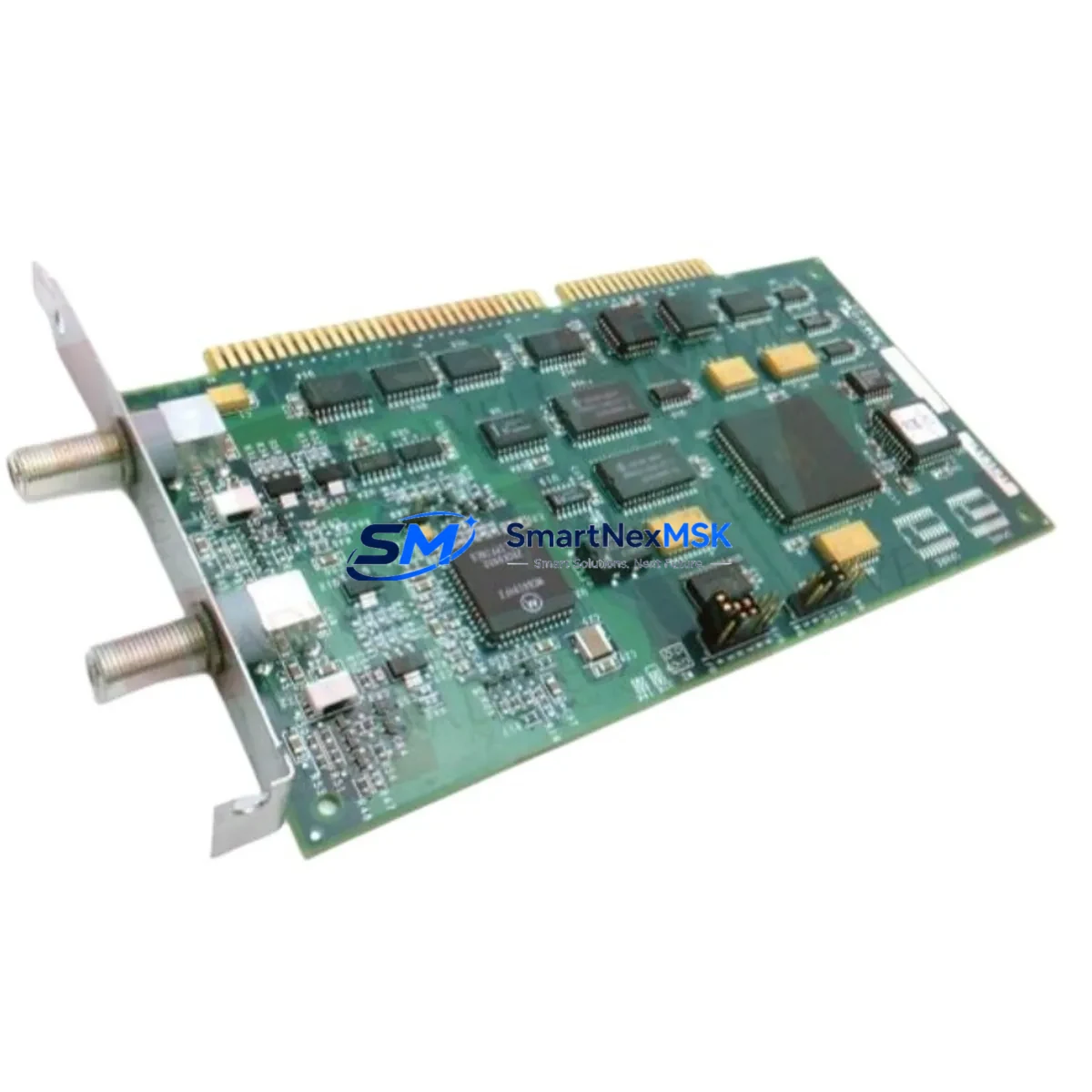
The 16267-1/4 is an ISA-bus communication interface card used in Siemens SINEC H1 and MODULNET M-NET industrial network environments. These networks were widely deployed across process automation, discrete manufacturing, and building automation systems throughout the 1990s and early 2000s. Many of these installations remain operational today, and sourcing compatible interface hardware has become increasingly difficult as original supply channels have dried up. SMARTNEXMSK maintains verified stock of the 16267-1/4 to support retrofit engineers who need a reliable, tested replacement without the lead times associated with new-generation migration projects.
Upgrade Compatibility Table
| Parameter | Details |
|---|---|
| SKU / Part Number | 16267-1/4 |
| Brand | Siemens |
| Module Type | ISA Bus Communication Interface Card |
| Network Compatibility | SINEC H1, MODULNET, M-NET |
| Bus Interface | ISA (Industry Standard Architecture) 16-bit |
| Communication Protocol | MODULNET / M-NET proprietary token-ring protocol |
| Replacement Scope | Direct drop-in for failed or EOL 16267-1/4 units in existing ISA-slot hosts |
| Installation Requirement | ISA-compatible host backplane or industrial PC with available ISA slot |
| Address Configuration | DIP switch or jumper-based I/O address and IRQ assignment (verify against original configuration) |
| Operating Environment | Industrial control cabinet; 0–55°C operating temperature |
| Retrofit Recommendation | Verify host BIOS ISA resource allocation; retain original driver and configuration files before swap |
| Warranty | 12-Month Warranty — tested before shipment |
Retrofit Planning for Existing Automation Systems
A successful retrofit of the 16267-1/4 requires a systematic review of the surrounding control architecture. Before removing the failed interface card, maintenance engineers should document the existing IRQ, I/O base address, and DMA channel assignments using the host system’s BIOS or configuration utility. These settings must be replicated on the replacement module to avoid address conflicts with other ISA peripherals such as serial communication cards or legacy fieldbus adapters.
In MODULNET environments, the 16267-1/4 typically operates alongside a Siemens SINEC H1 network controller or a CP 1430 TF communication processor. If the host industrial PC also carries a CP 5412 PROFIBUS interface or a CP 1613 Industrial Ethernet card, engineers must confirm that IRQ and memory address ranges do not overlap after the replacement card is installed. The SINEC NCM (Network Configuration Manager) software, if still in use, should be used to re-validate the network node address and token-ring participation parameters after the swap.
For systems where the host PC has been upgraded to a more modern platform but the MODULNET network must be preserved, engineers may need to source an ISA-to-PCI bridge adapter or an ISA expansion chassis to accommodate the 16267-1/4. In such cases, verifying the power supply capacity of the expansion chassis is essential — ISA cards can draw significant 5V current, and an undersized power supply unit (PSU) will cause intermittent communication faults that are difficult to diagnose.
The M-NET token-ring topology also requires that all nodes remain active for the ring to function. During the replacement procedure, plan for a controlled network shutdown rather than a hot-swap, as removing an active node without proper ring management can cause all remaining nodes to lose communication. Coordinate with the SIMATIC S5 PLC or SIMATIC S7 controller connected to the network to ensure that the CPU transitions to a safe STOP state before the interface card is removed. If the system includes a Siemens OP 17 or TP 27 HMI panel connected via MPI or PROFIBUS, verify that the HMI communication watchdog timeout is set appropriately to prevent spurious alarms during the maintenance window.
Terminal wiring on the MODULNET coaxial or twisted-pair segment should be inspected during the retrofit. Termination resistors at both ends of the segment must be confirmed to be within specification. If BNC connectors or AUI transceivers are used, inspect for corrosion or mechanical damage that may have contributed to the original communication failure. Replacing the interface card without addressing physical layer issues will result in recurring faults.
Downtime Control During System Migration
Minimizing downtime during a 16267-1/4 replacement requires preparation before the maintenance window begins. The most effective approach is to pre-configure the replacement card on a bench system using the same IRQ, I/O address, and DMA settings as the failed unit, then verify communication with a network analyzer or the SINEC NCM diagnostic tool before bringing the card to site. This pre-validation step eliminates the most common cause of extended downtime — configuration errors discovered only after the system is reassembled.
If the host industrial PC runs a real-time operating system such as MS-DOS with SINEC H1 drivers, retain a backup copy of the CONFIG.SYS, AUTOEXEC.BAT, and all SINEC driver initialization files. These files contain the hardware resource assignments and network node parameters that must be preserved across the card swap. A bootable backup disk or USB-to-IDE adapter with a cloned drive image is strongly recommended as a recovery option.
For systems where the MODULNET network connects to a higher-level SCADA or DCS platform, coordinate the maintenance window with the control room to ensure that the supervisory system is placed in manual mode and that all critical process interlocks are confirmed active before communication is interrupted. After the replacement card is installed and the network ring is restored, perform a full node poll using the network management software to confirm that all devices have rejoined the ring before returning the system to automatic control.
SMARTNEXMSK ships the 16267-1/4 with a functional test report confirming communication layer verification. Long-term supply continuity is supported through maintained inventory, ensuring that retrofit projects are not delayed by sourcing lead times. All units carry a 12-month warranty covering manufacturing defects and communication failures under normal operating conditions.
Retrofit Support FAQ
Q: Is the 16267-1/4 a direct drop-in replacement for the original Siemens unit?
A: Yes. The 16267-1/4 is a form-fit-function compatible replacement for the original Siemens ISA interface card used in MODULNET and M-NET environments. The IRQ, I/O address, and DMA settings must be configured to match the original unit using the onboard DIP switches or jumpers before installation.
Q: Can this module be used in a modern PC without an ISA slot?
A: The 16267-1/4 requires a physical ISA slot. For hosts without native ISA support, an ISA expansion chassis or ISA-to-PCI bridge is required. Compatibility with the bridge hardware must be verified against the host system’s chipset and BIOS ISA resource allocation capabilities.
Q: What testing is performed before shipment?
A: Each 16267-1/4 unit undergoes functional communication testing prior to shipment. A test report is included with the delivery. All units are covered by a 12-month warranty from the date of shipment, covering defects in materials and workmanship under normal industrial operating conditions.
Q: How do I confirm compatibility with my existing MODULNET network configuration?
A: Compatibility is confirmed by matching the module’s hardware revision, ISA bus width (16-bit), and network protocol version to your existing installation. SMARTNEXMSK’s technical team can assist with compatibility verification based on your system documentation, network topology diagram, or existing module label information. Contact sales@smartnexmsk.com with your system details.
© 2026 SMARTNEXMSK. All rights reserved.
Original Source: https://smartnexmsk.com
Contact: sales@smartnexmsk.com | +86 18259474341


