Siemens 16804-42 Retrofit-Ready Interface Module for SIMATIC Control Systems
The Siemens 16804-42 is a retrofit-ready electrical interface module engineered for seamless integration into legacy SIMATIC automation platforms. As industrial facilities face increasing pressure to modernize aging control infrastructure without full system overhauls, the 16804-42 provides a reliable, cost-effective path to upgrade obsolete or discontinued interface components while preserving existing rack architecture, wiring layouts, and program logic. Whether you are replacing a failed unit on a running production line or executing a planned migration from an older SIMATIC S5 or early S7 platform, this module delivers the electrical compatibility and mechanical fit required for a smooth transition.
Sourced directly from verified supply channels, each 16804-42 unit undergoes pre-shipment functional testing to confirm signal integrity, terminal continuity, and backplane communication. Stock is maintained for immediate dispatch, and all units are covered by a 12-month warranty against manufacturing defects and functional failure.
Upgrade Compatibility Table
| Parameter | Details |
|---|---|
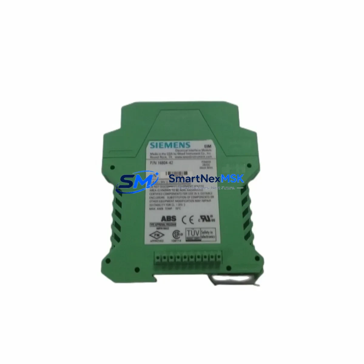
| SKU / Part Number | 16804-42 |
| Brand | Siemens |
| Series Compatibility | SIMATIC S5, SIMATIC S7-300 (interface tier) |
| Module Function | Electrical Interface / Signal Conditioning |
| Backplane Interface | Compatible with standard SIMATIC rack bus connectors |
| Installation Requirement | DIN rail or rack-mount; no additional adapter required |
| Terminal Wiring | Screw-terminal; matches legacy 16804-series pinout |
| Communication Compatibility | MPI, PROFIBUS DP (platform-dependent) |
| Replacement Recommendation | Direct drop-in for discontinued 16804-series variants |
| Commissioning Notes | Verify module address assignment in STEP 7 / TIA Portal before power-on |
| Warranty | 12 Months — covers functional failure and manufacturing defects |
| Pre-Shipment Test | Yes — signal integrity and terminal continuity verified |
Retrofit Planning for Existing Automation Systems
Successful retrofit of the Siemens 16804-42 into an existing control cabinet begins with a thorough audit of the current rack configuration. Engineers should document the slot assignment of the existing interface module within the SIMATIC rack — typically a UR1 or UR2 universal rack — and confirm that the power supply module, such as a Siemens PS 307 or equivalent, can sustain the additional current draw introduced by the replacement unit. Power budget verification is a critical first step that is frequently overlooked during emergency replacements.
Terminal wiring must be mapped against the original I/O schematic before disconnection. The 16804-42 uses a screw-terminal interface consistent with the broader 16804 family, which simplifies rewiring when replacing like-for-like. However, if the retrofit is part of a broader migration — for example, transitioning from a SIMATIC S5-115U or S5-135U platform to a modern S7-300 CPU 315-2 DP — engineers must account for differences in terminal block layout and signal voltage levels. In such cases, an SM 321 digital input module or SM 331 analog input module may need to be reconfigured alongside the interface module to maintain I/O fidelity.
Communication link integrity is equally important. If the existing system uses PROFIBUS DP, confirm that the CP 342-5 communications processor or equivalent is correctly addressed and that the GSD file for the updated configuration is loaded into the programming environment. For systems still operating on MPI, verify that the PC Adapter USB or MPI/DP programming cable used for STEP 7 access is compatible with the updated rack topology. HMI panels — such as a Siemens TP700 Comfort or legacy OP7 operator panel — should be tested for screen variable mapping after the module swap to ensure that all process values are correctly displayed and that alarm triggers remain intact.
For systems incorporating distributed I/O via ET 200M or ET 200S remote I/O stations, confirm that the interface module address does not conflict with existing DP slave addresses. Module address assignment should be validated in the hardware configuration (HW Config) within STEP 7 or TIA Portal before the replacement unit is powered on. A cold restart of the CPU — typically a CPU 315-2 DP or CPU 317-2 PN/DP — is recommended after module insertion to allow the system to re-enumerate the rack and confirm the new hardware configuration.
Downtime Control During System Migration
Minimizing unplanned downtime during a module replacement requires preparation that begins well before the maintenance window. The most effective approach is to upload and archive the current PLC program — including all data blocks, function blocks, and organization blocks — using STEP 7 or TIA Portal prior to any hardware change. This archived program serves as the recovery baseline if the replacement module triggers unexpected behavior during commissioning.
Where production schedules permit, a staged replacement strategy is recommended: install the 16804-42 in a test rack or spare cabinet slot, configure it offline, and validate communication and I/O mapping before swapping it into the live system. This approach reduces live-system exposure to under 15 minutes in most cases — limited to physical module swap, terminal reconnection, and a single CPU restart cycle.
For facilities where continuous control is mandatory, consider using a Siemens S7-400H redundant CPU architecture or a hot-standby configuration to allow module replacement without interrupting the control loop. In non-redundant systems, coordinate the maintenance window with the operations team to align with scheduled production breaks, and ensure that all field devices — including actuators, sensors, and safety relays — are in a safe state before power is removed from the rack. After module insertion and CPU restart, verify all I/O channels, confirm PROFIBUS DP communication status via the diagnostic buffer, and check HMI alarm logs before returning the system to automatic mode.
Retrofit Support FAQ
Q1: Is the Siemens 16804-42 a direct replacement for other 16804-series interface modules?
Yes. The 16804-42 is designed as a drop-in replacement within the 16804 product family. Terminal pinout, rack connector, and signal levels are consistent across the series. Minor firmware or configuration differences may apply depending on the target platform — confirm hardware revision compatibility in STEP 7 HW Config before finalizing the replacement.
Q2: What commissioning steps are required after installing the 16804-42?
After physical installation, assign the correct module address in the hardware configuration, perform a CPU cold restart, and verify that all I/O channels report correctly in the diagnostic buffer. For PROFIBUS DP systems, confirm DP slave status and check that the GSD file matches the installed module version. HMI variable mapping should be validated as a final step.
Q3: Can this module be used in systems still running SIMATIC S5 hardware?
The 16804-42 is primarily validated for SIMATIC S7-compatible rack environments. For S5 systems, compatibility depends on the specific rack and bus interface in use. We recommend providing your full system configuration — including CPU type, rack model, and existing module list — so our technical team can confirm fit before shipment.
Q4: What does the 12-month warranty cover, and how is it claimed?
The 12-month warranty covers functional failure and manufacturing defects under normal operating conditions. It does not cover damage resulting from incorrect installation, overvoltage, or environmental exposure beyond rated specifications. To initiate a warranty claim, contact our sales team with the order reference, a description of the fault, and photographic evidence of the installation. Replacement or repair will be arranged within 5 business days of claim approval.
© 2026 SMARTNEXMSK. All rights reserved.
Original Source: https://smartnexmsk.com
Contact: sales@smartnexmsk.com | +86 18259474341


