Siemens 6AV6642-0DA01-1AX1 Retrofit-Ready HMI Panel for SIMATIC OP177B Control Systems
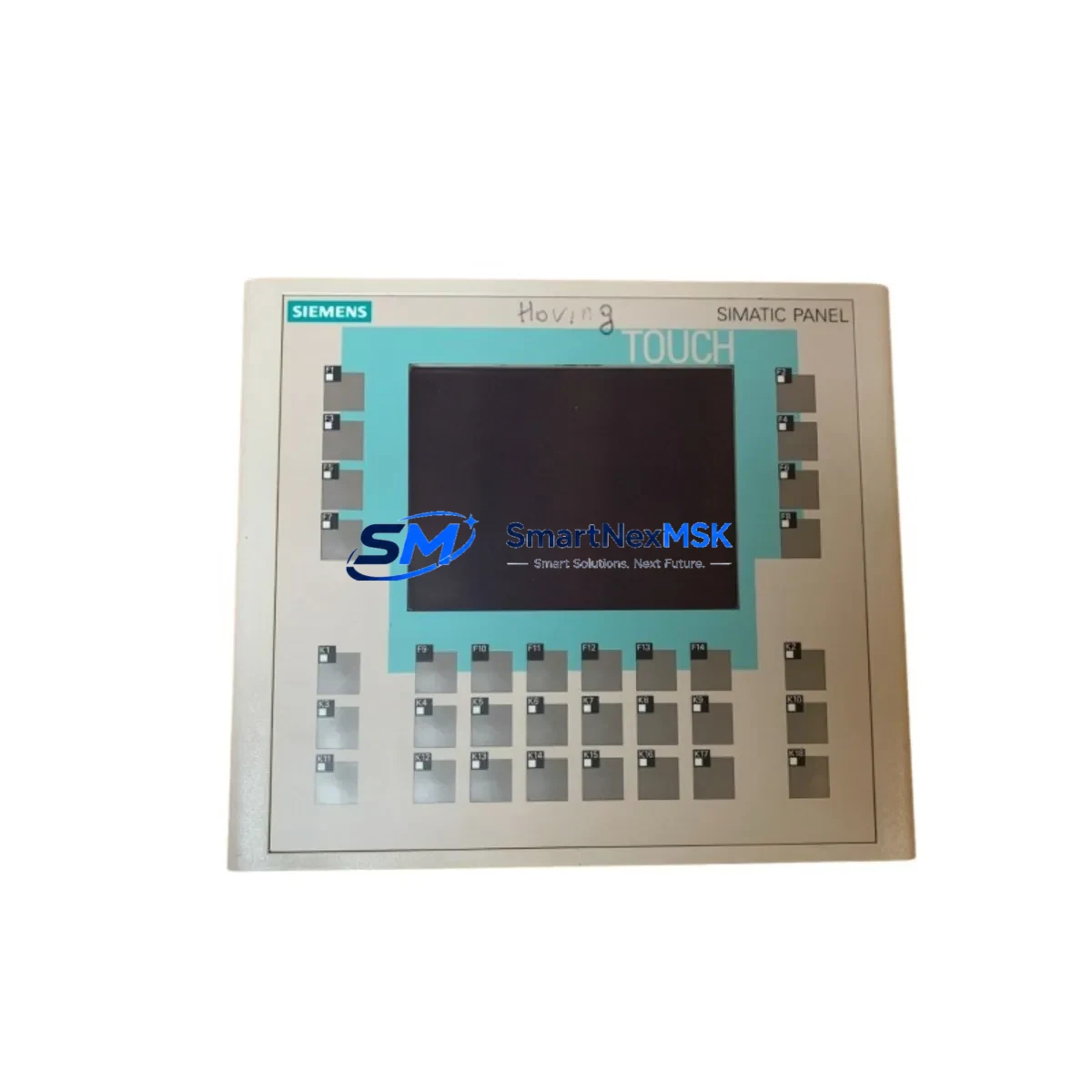
The Siemens 6AV6642-0DA01-1AX1 is a SIMATIC HMI OP177B operator panel engineered for demanding industrial environments. With a 5.7″ STN color display, integrated MPI/PROFIBUS DP and Ethernet interfaces, and full compatibility with the SIMATIC S7-300 and S7-400 controller families, this unit is the preferred retrofit solution for aging HMI installations across process automation, machine tool, and discrete manufacturing sectors. Whether you are replacing a failed panel, upgrading an obsolete OP170B or TP177B, or migrating a legacy SIMATIC S5-based control cabinet to a modern S7 architecture, the 6AV6642-0DA01-1AX1 delivers a proven, low-risk upgrade path with minimal engineering rework.
Sourced from verified supply channels and subject to pre-shipment functional testing, every unit shipped by SMARTNEXMSK is backed by a 12-month warranty. Stock is maintained to support urgent replacement orders, planned maintenance windows, and long-term spare-parts programs for facilities managing multiple SIMATIC HMI installations.
Upgrade Compatibility Table
| Parameter | Details |
|---|---|
| Part Number | 6AV6642-0DA01-1AX1 |
| Series | SIMATIC HMI OP177B |
| Display | 5.7″ STN Color, 320 × 240 px |
| Interface | MPI / PROFIBUS DP, RS-422/485, Ethernet (RJ45) |
| Compatible Controllers | SIMATIC S7-300, S7-400, S7-200 (via adapter), WinCC Flexible |
| Replaces / Upgrades | OP170B (6AV6542-0AA10-0AX0), TP177B, OP177A |
| Power Supply | 24 V DC (20.4–28.8 V), max. 6 W |
| Mounting | Panel cutout 197 × 141 mm, IP65 front protection |
| Communication Compatibility | PROFIBUS DP up to 12 Mbit/s; MPI 187.5 kbit/s – 12 Mbit/s |
| Retrofit Recommendation | Direct replacement for OP177B installations; verify WinCC Flexible project version before transfer |
| Commissioning Notes | Confirm MPI/PROFIBUS address, baud rate, and PLC data block mapping prior to startup |
| Warranty | 12 Months — covers hardware defects under normal operating conditions |
Retrofit Planning for Existing Automation Systems
Successful integration of the 6AV6642-0DA01-1AX1 into an existing control system begins well before the panel arrives on site. A structured retrofit plan reduces risk, protects the original program logic, and keeps the production line moving.
Power and wiring verification is the first checkpoint. The OP177B requires a stable 24 V DC supply with sufficient current capacity — confirm that the existing 24 V rail in the control cabinet, typically fed by a SITOP PSU100S or equivalent power supply module, can sustain the panel load alongside other connected devices such as the CPU module, SM321 digital input modules, and SM322 digital output modules. Check terminal block assignments against the original wiring diagram; the 9-pin Sub-D connector for MPI/PROFIBUS and the RJ45 Ethernet port must be routed correctly to avoid communication faults at startup.
Backplane and rack compatibility is not a concern for the OP177B since it is a standalone panel-mount HMI rather than a rack-inserted module. However, if the retrofit involves simultaneous replacement of CPU or I/O modules — for example, swapping an older CPU 315-2 DP for a CPU 317-2 DP/PN — the rack slot assignments, module addresses, and hardware configuration in STEP 7 or TIA Portal must be updated to reflect the new hardware. Failure to update the hardware configuration will result in configuration mismatch faults on the S7-300 rack.
Project file migration is a critical step when the original HMI project was created in ProTool or an early version of WinCC Flexible. The 6AV6642-0DA01-1AX1 is fully supported by WinCC Flexible 2008 SP4 and later. If the source project was built in ProTool/Pro CS, use the WinCC Flexible migration wizard to convert screens, tags, and alarm definitions. Verify that all tag connections reference the correct DB (data block) addresses in the S7 program — particularly if the CPU has been upgraded and the symbolic address table has changed.
Communication link configuration requires setting the correct MPI or PROFIBUS DP station address on the OP177B. This is done via the panel’s Start Center before the WinCC Flexible runtime is loaded. Ensure the baud rate matches the network setting on the CP 342-5 or CP 343-1 communication processor if one is present in the rack. For Ethernet-based connections to a CPU 317-2 PN/DP or a CP 343-1 Advanced, configure the IP address, subnet mask, and gateway directly on the panel and verify reachability before downloading the HMI project.
I/O expansion and peripheral devices connected to the same control cabinet — such as ET 200S distributed I/O stations, EM 277 PROFIBUS DP modules on S7-200 sub-networks, or TP 177A touch panels used as secondary operator stations — must remain operational during the HMI swap. Plan the replacement sequence so that the PROFIBUS DP master (the S7-300 CPU) continues to communicate with all slave devices while the OP177B is disconnected and the new panel is being configured.
Programming cable and download tools: use a PC Adapter USB A2 or SIMATIC NET CP 5611 card to connect the engineering station to the MPI network for project download. Confirm that the STEP 7 hardware configuration and the WinCC Flexible project are both consistent and compiled without errors before initiating the download to the new panel.
Downtime Control During System Migration
Minimizing unplanned downtime during an HMI retrofit requires a disciplined pre-outage preparation process. Before taking the system offline, back up the existing WinCC Flexible project from the old OP177B using the panel’s backup function or via the engineering PC. Archive the STEP 7 project, including the hardware configuration, symbol table, and all program blocks (OB, FB, FC, DB), to a secure location. This ensures that if the new panel exhibits unexpected behavior during commissioning, the original configuration can be restored rapidly.
During the physical swap, label all terminal connections and communication cables before disconnection. The MPI/PROFIBUS Sub-D connector, the 24 V DC power terminals, and any USB peripherals should be tagged to eliminate reconnection errors. The panel cutout dimensions for the 6AV6642-0DA01-1AX1 match the standard OP177B footprint (197 × 141 mm), so no mechanical modification to the cabinet door is required in a like-for-like replacement scenario.
After mounting and wiring the new panel, power it on and navigate to the Start Center to set the MPI/PROFIBUS address and baud rate before loading the runtime. Download the WinCC Flexible project, verify that all HMI screens display correctly, and confirm that tag values update in real time from the S7 CPU. Test all critical operator inputs — setpoint entries, mode selections, and alarm acknowledgements — before returning the line to production. A structured pre-startup checklist, covering power, communications, screen navigation, and alarm response, typically allows a trained technician to complete the commissioning phase within two to four hours, keeping the maintenance window within a single shift.
Retrofit Support FAQ
Q1: Is the 6AV6642-0DA01-1AX1 a direct drop-in replacement for the OP170B (6AV6542-0AA10-0AX0)?
The OP177B shares the same panel cutout dimensions and MPI/PROFIBUS interface as the OP170B, making it a mechanically and electrically compatible replacement. However, the HMI project must be migrated from ProTool to WinCC Flexible before downloading to the OP177B. The migration wizard in WinCC Flexible handles screen and tag conversion automatically, but manual review of alarm texts and recipe configurations is recommended.
Q2: What pre-shipment testing does SMARTNEXMSK perform on the 6AV6642-0DA01-1AX1?
Each unit undergoes power-on functional verification, display integrity check, and communication port continuity testing before dispatch. Units are shipped with original or equivalent protective packaging. A test report is available upon request for quality-controlled procurement processes.
Q3: Can this panel communicate with both PROFIBUS DP and Ethernet simultaneously?
Yes. The 6AV6642-0DA01-1AX1 supports concurrent MPI/PROFIBUS DP and Ethernet connections. This allows the panel to communicate with an S7-300 CPU via PROFIBUS while simultaneously connecting to a plant-level SCADA or data historian over Ethernet — a common requirement in hybrid retrofit projects where legacy field networks coexist with modern IT infrastructure.
Q4: What does the 12-month warranty cover, and how is a claim initiated?
The 12-month warranty covers hardware defects arising under normal operating conditions, including display failure, communication port malfunction, and power supply faults. Physical damage caused by incorrect wiring, overvoltage, or environmental exposure beyond the panel’s rated IP65 / IP20 (rear) protection class is excluded. To initiate a warranty claim, contact SMARTNEXMSK at sales@smartnexmsk.com with the order reference, a description of the fault, and photographic evidence. Replacement or repair is arranged within five business days of claim approval.
© 2026 SMARTNEXMSK. All rights reserved.
Original Source: https://smartnexmsk.com
Contact: sales@smartnexmsk.com | +86 18259474341


