Siemens 6AV6643-0BA01-1AX0 Retrofit-Ready HMI for S7 Control Systems: Seamless OP277 Compatibility & Legacy System Upgrade
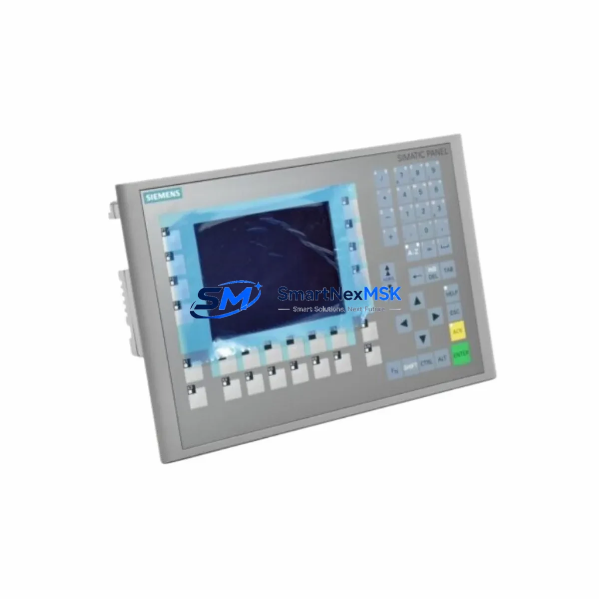
The Siemens 6AV6643-0BA01-1AX0 is a 6-inch color TFT HMI operator panel from the SIMATIC OP277 series, purpose-built for integration with Siemens S7-300 and S7-400 programmable logic controllers. As legacy OP270 and OP277 units reach end-of-service life across manufacturing plants, process facilities, and utility control rooms, the 6AV6643-0BA01-1AX0 has become the preferred retrofit solution for engineers seeking a direct, low-disruption replacement that preserves existing panel cutouts, PROFIBUS DP and MPI wiring, and WinCC flexible project files.
This unit supports both PROFIBUS DP and MPI communication protocols, making it fully compatible with existing S7-300 CPU modules such as the CPU 315-2 DP and CPU 317-2 DP, as well as S7-400 rack configurations. Engineers migrating from older OP7 or OP17 text-based panels will find the 6AV6643-0BA01-1AX0 a significant functional upgrade while maintaining backward compatibility with established network topologies.
Upgrade Compatibility Table
| Parameter | Detail |
|---|---|
| SKU / Part Number | 6AV6643-0BA01-1AX0 |
| Series | SIMATIC OP277 |
| Display | 6″ TFT Color, 320 × 240 px |
| Communication Interfaces | PROFIBUS DP, MPI (RS-485) |
| Compatible Controllers | S7-300, S7-400, S7-200 (via adapter) |
| Panel Cutout | Compatible with OP270 6″ cutout (192 × 138 mm) |
| Power Supply | 24 V DC (20.4–28.8 V), approx. 5 W |
| Replaces / Upgrades | OP7, OP17, OP27, OP270 6″, OP277 6″ |
| Engineering Software | WinCC flexible 2008 SP3 or later |
| Mounting | Panel flush-mount, IP65 front protection |
| Communication Compatibility | PROFIBUS DP up to 12 Mbit/s; MPI 187.5 kbit/s – 12 Mbit/s |
| Retrofit Recommendation | Direct drop-in for OP277 6″; adapter bracket required for OP27 |
| Commissioning Note | Verify MPI/PROFIBUS node address; re-download project via ProSave or WinCC flexible |
| Warranty | 12 Months — covers hardware defects, display, and communication ports |
Retrofit Planning for Existing Automation Systems
A successful retrofit of the 6AV6643-0BA01-1AX0 into an existing control cabinet begins with a thorough pre-installation audit. Engineers should first verify the 24 V DC power supply capacity available at the panel terminal strip — the OP277 draws approximately 5 W under normal operating conditions, but older SITOP PSU100S or SITOP modular power supply units in aging cabinets may already be operating near rated capacity when powering S7-300 SM321 digital input modules, SM322 digital output modules, and CP 342-5 PROFIBUS communication processors simultaneously.
Terminal wiring for the PROFIBUS DP connector (9-pin Sub-D) should be inspected for correct A/B line polarity and bus termination resistor status. In multi-drop PROFIBUS segments where the OP277 sits at the physical end of the cable run, the integrated termination resistors on the PROFIBUS connector must be enabled. If the panel is mid-segment, termination must be disabled to avoid signal reflection that can cause intermittent communication faults with the S7-300 CPU or ET 200S distributed I/O stations further along the bus.
Backplane and rack considerations are minimal for this HMI since it is a standalone panel-mount device rather than a rack-inserted module. However, engineers should confirm that the S7-300 rack — whether a UR1 universal rack or a CR3 compact rack — has sufficient CPU processing headroom to handle the additional HMI polling load, particularly in systems where a CP 343-1 Ethernet communication processor is already managing SCADA data exchange.
Module addressing for the OP277 is configured within WinCC flexible during project engineering. The MPI or PROFIBUS node address assigned to the panel must be unique within the network segment and must match the address stored in the HMI’s internal flash memory. When replacing a failed OP277 unit, engineers should retrieve the original node address from the plant documentation or read it from the defective unit using ProSave before the display becomes completely non-functional.
Program compatibility is a key concern during any HMI retrofit. Existing WinCC flexible projects compiled for the OP277 6″ device type are directly transferable to the 6AV6643-0BA01-1AX0 without screen layout changes, since both share the same 320 × 240 resolution and function key layout. Projects originally developed for the older OP270 6″ may require minor tag re-mapping if the communication driver configuration differs. HMI screen graphics, alarm lists, recipe data, and trend displays will transfer intact in most cases.
For sites where the control system also includes a TP177B touch panel or MP277 multi-panel operating in parallel for supervisory functions, the retrofit of the OP277 does not affect those devices’ communication links, provided the PROFIBUS segment addressing is maintained correctly. Similarly, S7-300 FM 355 closed-loop control modules and FM 351 positioning modules connected to the same CPU will continue to operate without interruption during the HMI swap, as long as the CPU remains in RUN mode throughout the panel exchange.
All units supplied by SMARTNEXMSK undergo pre-shipment functional testing including power-on verification, display pixel check, communication port continuity, and firmware version confirmation. Stock is maintained to support urgent replacement orders with short lead times.
Downtime Control During System Migration
Minimizing production downtime during an OP277 replacement is achievable with disciplined pre-staging. The recommended approach is to configure and test the replacement 6AV6643-0BA01-1AX0 offline before the scheduled maintenance window. Using a PC with WinCC flexible installed, engineers can load the existing project file, verify all tag connections, and perform a simulated communication test against a spare S7-300 CPU or a PLCSIM software instance.
During the physical swap, the S7-300 CPU should remain in RUN mode where process safety permits, allowing field devices — including frequency inverters, solenoid valve banks, and motor starters wired to SM322 output modules — to continue operating under the last valid output state. The HMI panel itself is not part of the control execution path; it is a visualization and operator input device only. Removing the OP277 from the PROFIBUS segment will generate a diagnostic alarm in the CPU’s diagnostic buffer but will not cause an emergency stop unless the application program has been written with an HMI watchdog interlock.
After physical installation, the new panel should be powered on and the PROFIBUS or MPI connection established before downloading the project. ProSave can be used to transfer the project via the MPI port if a direct PC-to-panel connection is preferred over network download. Once the project is loaded and the communication link is confirmed active — verified by checking the CPU’s online diagnostics in STEP 7 or TIA Portal — operators can resume normal HMI interaction within minutes.
For critical processes where even brief HMI unavailability is unacceptable, a parallel commissioning approach is recommended: install the new 6AV6643-0BA01-1AX0 on a temporary panel mount adjacent to the existing unit, establish its PROFIBUS connection on a separate node address, verify all screens and alarms, then cut over by reassigning the node address and removing the old panel — all within a single shift.
Retrofit Support FAQ
Q1: Is the 6AV6643-0BA01-1AX0 a direct replacement for the OP277 6″ (6AV6643-0BA01-1AX0)?
Yes. The 6AV6643-0BA01-1AX0 is the OP277 6″ panel. It is a direct like-for-like replacement for any failed or end-of-life unit of the same part number. No mechanical adapter, wiring modification, or software conversion is required. The replacement unit accepts the same WinCC flexible project file and uses the same PROFIBUS DP / MPI connector pinout.
Q2: Can this panel communicate with an S7-400 CPU via PROFIBUS DP?
Yes. The 6AV6643-0BA01-1AX0 supports PROFIBUS DP at speeds up to 12 Mbit/s and is fully compatible with S7-400 CPUs including the CPU 412-2 DP and CPU 416-3 DP. Ensure the HMI’s PROFIBUS node address is configured correctly in WinCC flexible and that the bus termination on the physical connector matches the panel’s position in the segment.
Q3: What commissioning steps are required after installing the replacement panel?
After physical installation and power-on, connect a PC via MPI or PROFIBUS and use ProSave or WinCC flexible to download the project file. Verify the node address matches the original configuration. Confirm communication is active by checking the CPU diagnostic buffer in STEP 7 — the HMI should appear as an active node. Test all operator screens, alarm acknowledgments, and recipe functions before returning the system to production. The entire commissioning process typically takes 30–90 minutes for a prepared engineer.
Q4: What does the 12-month warranty cover, and how is it claimed?
The 12-month warranty covers hardware defects including display failure, communication port malfunction, power supply faults, and keypad/touchscreen failure under normal operating conditions. It does not cover damage from incorrect wiring, overvoltage, or physical impact. To claim warranty service, contact SMARTNEXMSK with the order reference and a description of the fault. Units are inspected and either repaired or replaced within the agreed service lead time. Warranty claims do not affect the customer’s remaining stock or ongoing orders.
© 2026 SMARTNEXMSK. All rights reserved.
Original Source: https://smartnexmsk.com
Contact: sales@smartnexmsk.com | +86 18259474341


