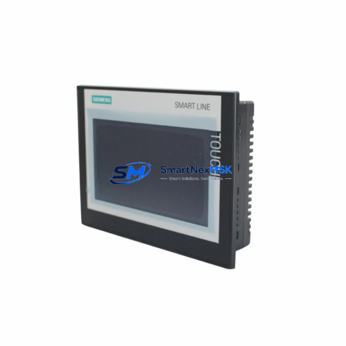
Siemens 6AV6648-0CC11-3AX0 Retrofit-Ready HMI for SMART 700 IE Control Systems
The Siemens 6AV6648-0CC11-3AX0 is a 7-inch widescreen SIMATIC SMART 700 IE V3 HMI panel engineered for seamless integration into existing SIMATIC S7-200 SMART and S7-1200 control architectures. As legacy SMART 700 IE V2 units reach end-of-life and spare parts become increasingly scarce, the 6AV6648-0CC11-3AX0 serves as the definitive retrofit-ready replacement — preserving your existing panel cutout dimensions, terminal wiring layout, and PROFINET/Ethernet communication links without requiring structural modifications to the control cabinet.
For engineers managing aging production lines, the 6AV6648-0CC11-3AX0 delivers a critical advantage: it maintains backward compatibility with WinCC flexible Compact and SIMATIC WinCC Basic project files, allowing existing HMI screen configurations, alarm lists, and tag mappings to be migrated with minimal rework. This dramatically reduces engineering hours during panel changeovers and keeps downtime windows tight — a decisive factor in continuous-process environments where every hour of unplanned shutdown carries measurable cost.
Our inventory of the 6AV6648-0CC11-3AX0 is sourced from verified distribution channels, pre-tested against factory firmware baselines, and shipped with a 12-month warranty covering hardware defects under normal operating conditions. Each unit undergoes outgoing inspection including display calibration, communication port verification, and power-on functional testing before dispatch from our Xiamen facility.
Upgrade Compatibility Table
| Parameter | 6AV6648-0CC11-3AX0 (SMART 700 IE V3) | Legacy 6AV6648-0BC11-3AX0 (V2) |
|---|---|---|
| Display Size | 7″ Widescreen TFT, 800×480 | 7″ Widescreen TFT, 800×480 |
| Panel Cutout | 192 × 138 mm (direct fit) | 192 × 138 mm |
| Communication | PROFINET, Ethernet (RJ45 ×2) | Ethernet (RJ45 ×1) |
| USB Interface | USB-A Host + USB-B Device | USB-A Host only |
| Power Supply | 24 V DC (20.4–28.8 V) | 24 V DC (20.4–28.8 V) |
| Project Migration | WinCC Basic / WinCC flexible Compact | WinCC flexible Compact |
| PLC Compatibility | S7-200 SMART, S7-1200, S7-300 | S7-200 SMART, S7-200 |
| Installation | Panel mount, IP65 front | Panel mount, IP65 front |
| Commissioning Note | Verify PROFINET device name assignment | N/A |
| Warranty | 12 Months (SMARTNEXMSK) | Manufacturer EOL |
Retrofit Planning for Existing Automation Systems
A successful retrofit of the 6AV6648-0CC11-3AX0 into an operational control cabinet begins well before the physical swap. The first step is a power budget audit: confirm that the existing 24 V DC rail — typically supplied by a SITOP PSU100S or equivalent DIN-rail power supply — can sustain the panel’s 6 W typical load alongside co-located components such as the CPU module, signal modules, and any active communication processors. Undersized power supplies are a leading cause of intermittent HMI faults post-retrofit.
Terminal wiring on the 6AV6648-0CC11-3AX0 uses a standard 2-pin DC connector compatible with the V2 predecessor, so existing cable harnesses can be reused without re-termination. However, engineers should inspect conductor insulation and ferrule crimps — particularly in high-vibration environments — before reconnecting. The dual RJ45 PROFINET ports introduce a new topology option: the panel can now participate in a PROFINET ring or linear chain alongside other devices such as ET 200SP distributed I/O stations or IM 151-3 PN interface modules, enabling more flexible cabinet layouts.
Backplane and rack considerations are straightforward for standalone panel installations, but in integrated control cabinets housing SIMATIC S7-300 racks with SM 321 digital input modules or SM 322 digital output modules, verify that the HMI’s Ethernet cable routing does not introduce EMI coupling from adjacent frequency inverters or servo drives. Shielded Cat5e or Cat6 cabling with proper grounding at one end is strongly recommended.
Module addressing requires attention when migrating from a V2 project: if the original WinCC flexible project used a direct S7 connection over MPI/DP via a PC adapter cable, the V3 panel’s Ethernet-native architecture requires reconfiguring the PLC connection to use S7 protocol over TCP/IP. This involves updating the PLC IP address, rack, and slot parameters in the HMI project’s connection manager — a 15-minute task that is often overlooked and causes post-commissioning communication failures.
For sites running SIMATIC WinCC flexible 2008 SP5 or earlier, project conversion to WinCC Basic V16 or later is required before downloading to the V3 panel. The conversion wizard handles most screen objects, but custom scripts referencing deprecated system tags — particularly those tied to the OP communication driver — must be manually reviewed. Allocate one to two engineering hours for projects with more than 50 screens or complex alarm configurations. Once converted, the project can be transferred via USB stick or direct Ethernet download, eliminating the need for a dedicated programming cable such as the PC/PPI cable used with older S7-200 systems.
Downtime Control During System Migration
Minimizing production interruption during an HMI panel swap requires a structured pre-outage preparation protocol. Before the maintenance window opens, export the current HMI project from the V2 panel using a USB stick and archive it alongside a full PLC program backup — use STEP 7 Micro/WIN SMART to upload the S7-200 SMART CPU program and save it with version annotation. This ensures that if the migration encounters an unexpected issue, the original control logic can be restored within minutes rather than hours.
During the physical swap, the control system’s PLC continues executing its scan cycle independently of the HMI panel. For processes where operator visibility is critical during the changeover — such as temperature-controlled batch reactors or conveyor sequencing lines — consider deploying a temporary SIMATIC KTP400 Basic panel or a laptop running WinCC Runtime Advanced connected to the PLC via Ethernet as a monitoring bridge. This keeps operators informed of process states without halting production.
After mounting the 6AV6648-0CC11-3AX0 and restoring power, the commissioning sequence should follow this order: verify 24 V DC supply voltage at the panel connector, confirm Ethernet link LEDs are active on both the panel and the managed switch port, download the converted HMI project, assign the PROFINET device name if applicable, and perform a full screen navigation test covering all process pages, alarm acknowledgment functions, and recipe management screens. Document the commissioning results and retain them with the panel’s serial number for warranty reference.
Total planned downtime for a straightforward V2-to-V3 swap on a well-prepared site typically runs 2 to 4 hours, including project conversion, physical installation, and functional verification. Sites with complex multi-panel architectures or legacy MPI network segments should budget additional time for communication reconfiguration.
Retrofit Support FAQ
Q1: Is the 6AV6648-0CC11-3AX0 a direct drop-in replacement for the 6AV6648-0BC11-3AX0 (SMART 700 IE V2)?
A: Yes for mechanical and power wiring — the panel cutout dimensions (192 × 138 mm) and 24 V DC terminal connector are identical. The key difference is communication: the V3 adds a second RJ45 PROFINET port and drops the MPI/DP interface. Projects using MPI connections must be reconfigured to Ethernet/S7 protocol before the V3 panel will communicate with the PLC.
Q2: What commissioning steps are required after installation?
A: After physical installation and power-on, assign the PROFINET device name via the panel’s Start Center if your network uses PROFINET IO. Download the HMI project via USB or Ethernet, verify all PLC tag connections are online, test alarm triggers, and confirm recipe read/write functions. Log the panel’s MAC address and serial number for warranty registration.
Q3: Can I reuse my existing terminal wiring and cabinet cutout?
A: Yes. The 2-pin DC power connector and panel cutout are mechanically compatible with the V2 predecessor. Ethernet cabling can be reused if it meets Cat5e or better specification. No sheet metal modification is required for standard panel mount installations.
Q4: What does the 12-month warranty cover, and how is it claimed?
A: The 12-month warranty covers hardware defects under normal operating conditions — including display, touchscreen, communication ports, and power input circuitry. It does not cover damage from incorrect wiring, overvoltage, or physical impact. To claim warranty service, contact sales@smartnexmsk.com with the panel serial number, purchase date, and a description of the fault. Replacement or repair is arranged within 5 business days of fault confirmation.
© 2026 SMARTNEXMSK. All rights reserved.
Original Source: https://smartnexmsk.com
Contact: sales@smartnexmsk.com | +86 18259474341


