Siemens 6ED1052-1MD00-0BA7 Retrofit-Ready Display Module for LOGO! Control Systems
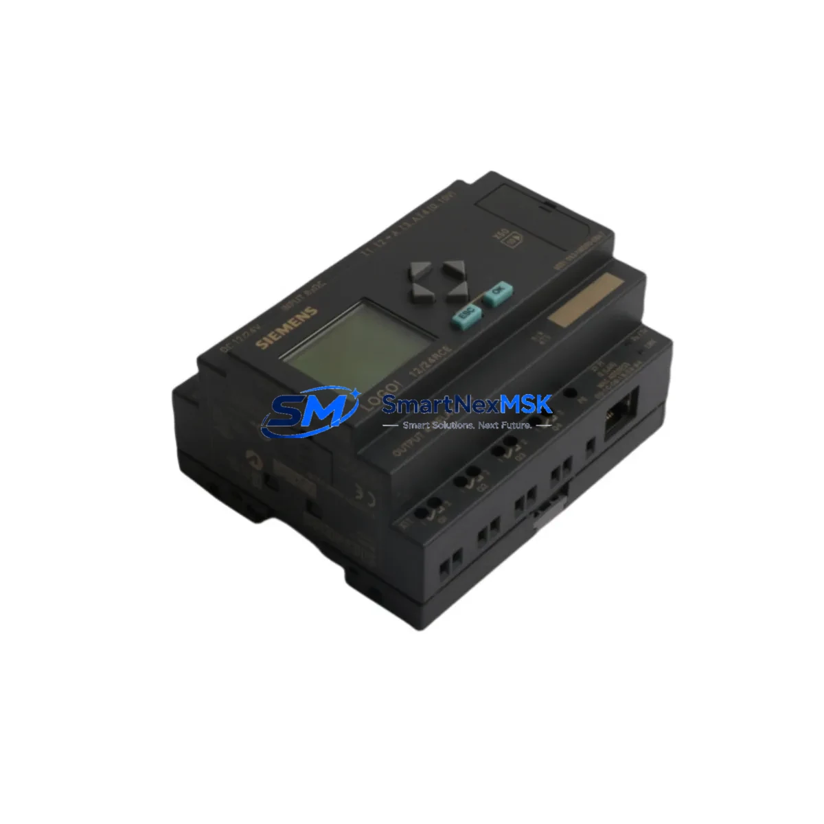
The Siemens 6ED1052-1MD00-0BA7 is the dedicated text display and operator keypad module for the LOGO! 0BA7 series compact logic controller. Designed as a direct plug-in accessory to the LOGO! 12/24RCE, LOGO! 230RCE, and LOGO! 24CE base units, this module provides on-site parameter adjustment, program monitoring, and real-time status display without requiring a connected PC or LOGO!Soft Comfort programming software. For facilities managing aging LOGO! 0BA6 or 0BA7 installations, sourcing a verified replacement 6ED1052-1MD00-0BA7 is often the fastest path to restoring operator visibility and avoiding full controller replacement.
SMARTNEXMSK maintains ready stock of the 6ED1052-1MD00-0BA7 and ships globally with full pre-shipment functional testing and a 12-month warranty. Each unit is inspected for connector integrity, display clarity, and keypad response before dispatch.
Upgrade Compatibility Table
| Parameter | Details |
|---|---|
| Compatible Base Units | LOGO! 0BA7 series: 6ED1052-1MD00-0BA8, 6ED1052-1HB00-0BA8, 6ED1052-2MD00-0BA8, 6ED1052-2HB00-0BA8; also backward-compatible with select 0BA6 variants |
| Interface / Connector | Proprietary LOGO! front-panel snap-fit connector; no additional wiring required |
| Communication Compatibility | Direct bus connection to LOGO! base unit; no Ethernet or serial protocol configuration needed |
| Installation Requirement | Power-off base unit before attaching or detaching display module; snap into front slot until audible click |
| Replacement Recommendation | Direct drop-in replacement for failed or damaged 6ED1052-1MD00-0BA7 units; no program re-upload required |
| Commissioning Notes | After installation, verify display initializes correctly and all function keys respond; test parameter read/write via keypad |
| Warranty | 12 months from date of shipment; covers manufacturing defects and display/keypad failure under normal operating conditions |
Retrofit Planning for Existing Automation Systems
When modernizing a LOGO! 0BA7-based control panel, the display module is rarely the only component under review. A typical retrofit scenario involves the LOGO! base unit itself — such as the 6ED1052-1MD00-0BA8 (0BA8 generation successor) — alongside the LOGO! Power 24V/2.5A power supply module (6EP1332-1SH43) that feeds the controller rack. Engineers frequently discover that the existing 24 VDC rail is undersized once additional I/O expansion modules are added, making power capacity verification a mandatory first step before any hardware swap.
For installations requiring additional digital inputs or outputs beyond the base unit’s onboard I/O, the LOGO! DM8 12/24R digital expansion module (6ED1055-1MB00-0BA2) is the standard extension choice within the 0BA7 ecosystem. When analog process values — such as temperature or pressure — must be monitored, the LOGO! AM2 analog input module (6ED1055-1MA00-0BA2) provides two 0–10 V or 0–20 mA channels compatible with the 0BA7 bus architecture.
Terminal wiring is another critical checkpoint. LOGO! 0BA7 base units use push-in or screw-type terminals depending on the variant; replacement modules must match the existing terminal block pitch and wire gauge to avoid rework. If the control cabinet also houses a Siemens SIMATIC S7-200 CPU 224 or a LOGO! 8 (0BA8) base unit as part of a phased migration, engineers should document the existing LOGO!Soft Comfort program (.lsc file) and verify that function block libraries used in the 0BA7 program are supported in the target platform before decommissioning the original controller.
Communication link integrity is equally important in mixed-generation panels. If the LOGO! 0BA7 is connected to a LOGO! TD (Text Display) or interfaces with a Siemens KTP400 Basic HMI panel via Modbus or Ethernet/IP, the display module replacement must not interrupt the communication address mapping. Confirm that the LOGO! base unit’s network parameters remain unchanged after the module swap, and re-validate all HMI screen tag bindings before returning the system to production.
For sites using a LOGO! CMR2020 communication module for remote SMS or cloud monitoring, verify that the CMR module’s configuration is preserved independently of the display module, as the two components operate on separate interfaces. Programming cables such as the LOGO! PC cable (6ED1057-1AA01-0BA0) should be on hand during commissioning to allow direct laptop connection for program verification if the display module is temporarily unavailable during the swap sequence.
Downtime Control During System Migration
Minimizing production downtime during a LOGO! display module replacement requires a structured pre-outage preparation protocol. Before scheduling the maintenance window, export the complete LOGO! program from the base unit using LOGO!Soft Comfort and store a timestamped backup on a secure network drive. Photograph or document all terminal wiring connections, especially if the control cabinet has been modified since original commissioning and wiring labels are worn or missing.
During the outage, power down the LOGO! base unit and any connected expansion modules — including DM8 digital modules and AM2 analog modules — before removing the display module. The snap-fit connector is designed for tool-free removal, but applying lateral force rather than direct pull reduces the risk of connector pin damage. Install the replacement 6ED1052-1MD00-0BA7, restore power, and confirm the display initializes to the home screen within 5 seconds. If the display shows a fault code, cross-reference the LOGO! 0BA7 system manual (A5E02481235) before proceeding.
Once the display is confirmed operational, perform a full I/O scan: verify that all digital inputs reflect correct field device states, all digital outputs actuate as expected under manual test mode, and any analog channels read within calibrated range. Re-enable any connected HMI panels and confirm that all operator screens display live data correctly. Document the completed swap in the site maintenance log, including the replacement unit’s serial number and the date of installation, to support future warranty claims and audit trails.
Retrofit Support FAQ
Q1: Is the 6ED1052-1MD00-0BA7 a direct replacement for the original display module on my LOGO! 0BA7 base unit?
Yes. The 6ED1052-1MD00-0BA7 is the OEM-specified display and keypad module for LOGO! 0BA7 base units. It connects via the proprietary front-panel interface and requires no program modification or address reconfiguration after installation.
Q2: Will replacing the display module erase the program stored in the LOGO! base unit?
No. The program is stored in the LOGO! base unit’s internal memory, not in the display module. Swapping the display module does not affect the stored program, retentive data, or network configuration of the base unit. As a precaution, always back up the program before any hardware maintenance.
Q3: What wiring or terminal changes are required when installing the replacement module?
None. The 6ED1052-1MD00-0BA7 connects exclusively through the snap-fit front-panel bus connector on the LOGO! base unit. There are no external terminal connections, power wires, or communication cables to modify. The only requirement is that the base unit is powered off during installation.
Q4: Does SMARTNEXMSK test units before shipment, and what does the 12-month warranty cover?
Yes. Every 6ED1052-1MD00-0BA7 unit undergoes pre-shipment functional testing covering display initialization, keypad response, and connector integrity. The 12-month warranty covers manufacturing defects and component failure under normal operating conditions. Units showing physical damage caused by incorrect installation or overvoltage are not covered under warranty terms.
© 2026 SMARTNEXMSK. All rights reserved.
Original Source: https://smartnexmsk.com
Contact: sales@smartnexmsk.com | +86 18259474341


