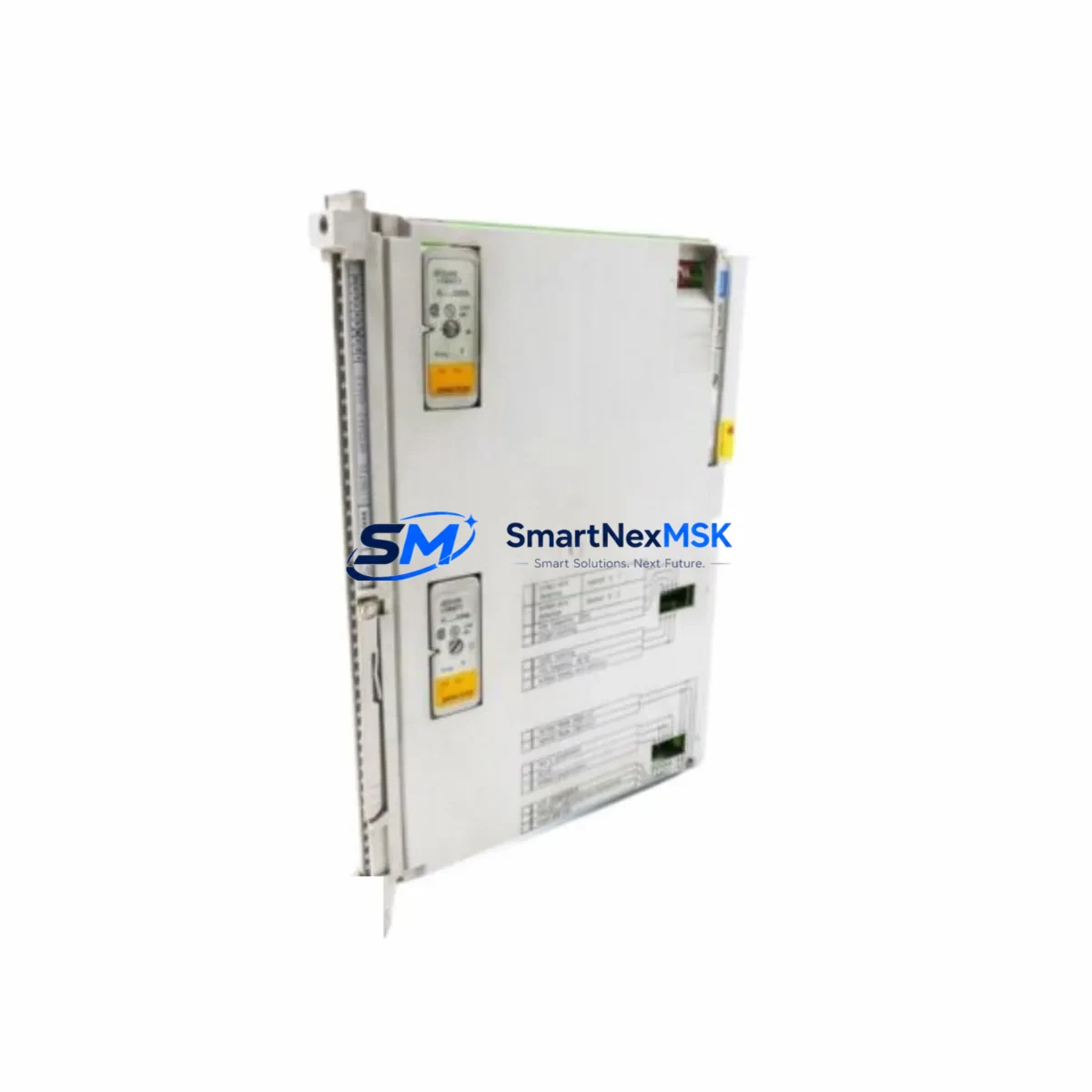
SIEMENS 6ES5460-4UA12 Maintenance-Ready Spare for SIMATIC S5 Automation
The SIEMENS 6ES5460-4UA12 is an original analog input module designed for the SIMATIC S5 programmable logic controller platform — one of the most widely deployed legacy automation systems in process industries, discrete manufacturing, and utility infrastructure worldwide. As SIMATIC S5 systems age beyond their original design life, the availability of verified, original-specification spare parts becomes the single most critical factor in preventing unplanned downtime and extending system service life. This listing provides maintenance engineers and procurement teams with a directly sourced, tested, and warranty-backed replacement module ready for immediate deployment.
Whether you are managing a scheduled turnaround, responding to an emergency fault, or building a strategic spare parts buffer for a long-running S5 installation, the 6ES5460-4UA12 is a precision-matched replacement that eliminates the risk of signal drift, configuration mismatch, or compatibility failure associated with non-original substitutes. Each unit is inspected, function-tested, and shipped with full documentation support.
Spare Maintenance Table
| Parameter | Specification / Detail |
|---|---|
| Part Number / SKU | 6ES5460-4UA12 |
| Brand | SIEMENS |
| Series | SIMATIC S5 |
| Module Type | Analog Input Module |
| Number of Channels | 8 channels (inferred from S5-460 series standard) |
| Input Signal Range | ±10 V / 0–20 mA / 4–20 mA (configurable per channel) |
| Resolution | 12-bit (inferred, S5 analog standard) |
| Compatible PLC Rack | SIMATIC S5-115U, S5-135U, S5-155U |
| Backplane Interface | S5 parallel bus (EU/ER rack) |
| Supply Voltage | 24 V DC (via backplane) |
| Operating Temperature | 0 °C to +60 °C |
| Mounting | S5 expansion rack slot (EU 183 / EU 185 / ER 701) |
| Country of Origin | Germany |
| Compatibility Verified | SIMATIC S5 series (drop-in replacement) |
| Condition | Original / Surplus / Refurbished (tested) |
| Warranty | 12 Months |
| Lead Time | In stock — ships within 1–3 business days |
| Export Control | Compliant — contact for EAR/ECCN documentation |
Maintenance Planning for Continuous Operation
Replacing the 6ES5460-4UA12 in a live SIMATIC S5 installation is rarely an isolated task. Experienced maintenance engineers know that an analog input fault often signals broader stress on the surrounding electrical and control infrastructure. Before returning the system to service, a thorough inspection of the following components is strongly recommended:
Power Supply Module (e.g., 6ES5955-3LC41 or 6ES5951-7LD21): Verify output voltage stability under load. A degraded S5 power supply can cause intermittent analog signal errors that mimic module failure. Measure ripple and confirm 24 V DC rail integrity before commissioning the replacement 6ES5460-4UA12.
Signal Cables and Terminal Blocks: Inspect all field wiring connected to the analog input channels. Corroded terminals, loose ferrules, or damaged shielding on signal cables introduce noise that corrupts 4–20 mA and voltage readings. Replace any suspect terminal blocks (e.g., Phoenix Contact or Weidmüller DIN-rail types) and re-terminate shielded pairs with proper grounding at one end only.
Signal Isolators and Barriers: If the analog inputs are sourcing signals from field transmitters in hazardous areas or across long cable runs, check the associated signal isolators (e.g., SIEMENS SITRANS or equivalent DIN-rail isolators). A failed isolator can present as an analog input module fault and will cause the same symptoms after module replacement if not addressed.
I/O Bus Connector and Backplane: Inspect the S5 rack backplane connector pins for oxidation or mechanical damage. The 6ES5460-4UA12 interfaces via the S5 parallel bus, and poor backplane contact is a common root cause of intermittent analog faults in aging racks. Clean contacts with appropriate contact spray and verify seating torque.
CPU Module (e.g., 6ES5948-3UA11 or 6ES5928-3UB21): After installing the replacement analog input module, confirm that the CPU recognizes the new module in the hardware configuration. In some S5 installations, the CPU module’s battery-backed RAM retains the old module address; a cold restart or configuration reload may be required. If the CPU module itself shows signs of battery depletion or memory errors, address this concurrently to avoid a second unplanned outage.
Digital Output Modules and Relay Cards: In mixed analog/digital control cabinets, check adjacent digital output modules (e.g., 6ES5470-4UA12) and relay output cards for signs of coil burnout or contact wear. Analog input faults sometimes originate from ground loops introduced by failing relay coils sharing the same 24 V DC supply rail.
Communication Modules (e.g., CP 5431 or CP 5511): If the S5 system communicates via PROFIBUS or Industrial Ethernet, verify that the communication processor module is operating normally after the analog input replacement. A module swap can occasionally trigger a bus fault if the rack configuration is not refreshed in the programming software (STEP 5 or STEP 7 in S5-compatible mode).
Fuses and Circuit Protection: Check all fuse holders in the control cabinet associated with the 24 V DC analog supply circuit. Replace any slow-blow fuses that show signs of thermal stress. A marginally blown fuse that has not fully opened can cause erratic analog readings and is easily overlooked during fault isolation.
Maintaining a minimum stock of one spare 6ES5460-4UA12 per critical production line, alongside a matched power supply module and a set of terminal block connectors, is the industry-standard approach for S5 installations where downtime costs exceed the cost of the spare inventory. For multi-rack installations, consider stocking one spare analog input module per rack as part of your annual maintenance budget cycle.
Site Replacement Workflow
Step 1 — Isolation and Lockout/Tagout: De-energize the S5 rack following your site LOTO procedure. Confirm 24 V DC supply is isolated at the cabinet breaker before touching any module.
Step 2 — Document Current Configuration: Before removing the faulty 6ES5460-4UA12, photograph the wiring, record the slot address, and note any DIP switch or jumper settings on the module face. The S5-460 series uses hardware switches to configure input ranges per channel — these settings must be replicated exactly on the replacement unit.
Step 3 — Module Removal: Release the module locking lever, disconnect the front connector (20-pin or 40-pin depending on variant), and slide the module out of the rack slot. Handle by the frame only — avoid touching the PCB or connector pins.
Step 4 — Configure Replacement Module: Set the DIP switches on the 6ES5460-4UA12 replacement to match the documented configuration. Verify input range selection (voltage/current) matches the field transmitter output type for each channel.
Step 5 — Install and Re-energize: Seat the replacement module firmly into the rack slot, reconnect the front connector, and restore power. Observe the module status LED — a steady green indicates normal operation. A flashing or red LED indicates a configuration or wiring fault.
Step 6 — Functional Verification: Using STEP 5 or a compatible S5 programming tool, monitor the analog input values in real time. Apply a known reference signal (e.g., a calibrated 4–20 mA loop calibrator) to each channel and verify the PLC reads the expected engineering unit value within the specified accuracy band.
Step 7 — Return to Service and Documentation: Update the maintenance log with the replacement date, module serial number, and test results. Tag the removed module for evaluation and potential refurbishment. Notify the procurement team to replenish the spare parts stock.
This workflow is applicable to all SIMATIC S5 analog input module variants in the 6ES5460 family and can be adapted for similar replacement procedures on adjacent modules in the same control cabinet.
Spare Parts Support FAQ
Q1: Is the 6ES5460-4UA12 still available as a new original part, or is this a refurbished unit?
The SIMATIC S5 series has been officially discontinued by SIEMENS, and new production units are no longer manufactured. Units available through specialist industrial spare parts suppliers like SMARTNEXMSK are sourced from verified surplus stock, decommissioned equipment, or professionally refurbished inventory. Each unit undergoes functional testing before shipment. The 12-month warranty covers all tested parameters and applies from the date of delivery.
Q2: How do I verify compatibility before ordering?
The 6ES5460-4UA12 is compatible with all SIMATIC S5 racks that support the S5 parallel bus interface, including the S5-115U, S5-135U, and S5-155U central controllers. Confirm your rack model and slot availability before ordering. If you are unsure, provide your CPU module part number and rack configuration to our technical team at sales@smartnexmsk.com and we will confirm compatibility before shipment.
Q3: What testing is performed before shipment?
Each 6ES5460-4UA12 unit is powered up in a SIMATIC S5 test rack, all analog input channels are verified against reference signals across the full configured input range, and the module bus interface is confirmed error-free. Units that fail any test parameter are quarantined and not shipped. A test report is available upon request for critical applications.
Q4: What is the recommended spare parts stocking strategy for S5 analog input modules?
For production-critical S5 installations, we recommend maintaining a minimum of one 6ES5460-4UA12 per active rack as on-site hot spare inventory. For facilities with multiple S5 systems, a centralized spare parts store with two to three units per module type provides adequate coverage for most failure scenarios. Given the discontinuation of the S5 platform, procurement lead times from the open market can be unpredictable — securing buffer stock now is strongly advisable to protect against future supply gaps.
© 2026 SMARTNEXMSK. All rights reserved.
Original Source: https://smartnexmsk.com
Contact: sales@smartnexmsk.com | +86 18259474341


