Siemens 6ES5470-4UA12 Retrofit-Ready Analog Output for S5: Compatible Modernization & Smooth System Upgrade
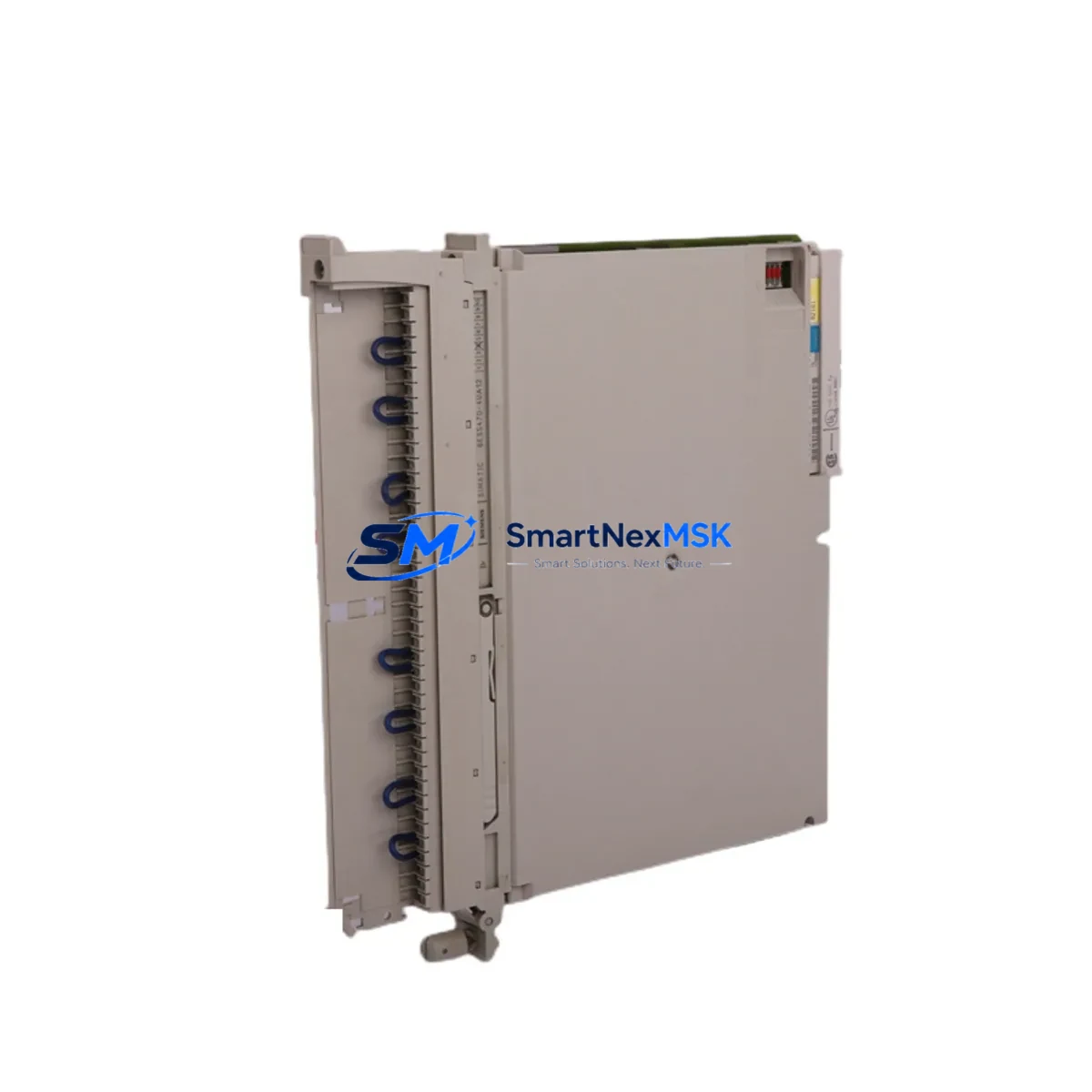
The Siemens 6ES5470-4UA12 is an 8-channel analog output module originally designed for the SIMATIC S5 programmable controller platform. As SIMATIC S5 systems approach end-of-life and spare parts become increasingly scarce, the 6ES5470-4UA12 remains a critical component for facilities that must maintain continuous production while planning a phased migration to modern control architectures. SMARTNEXMSK maintains verified stock of this module to support retrofit projects, emergency replacements, and long-term maintenance contracts across manufacturing, chemical processing, power generation, and infrastructure industries.
Each unit is functionally tested prior to shipment, supplied with a 12-month warranty, and accompanied by documentation to support your engineering team during installation and commissioning. Whether you are replacing a failed module on an active production line or building a spare-parts buffer for a legacy SIMATIC S5 rack, the 6ES5470-4UA12 delivers the signal integrity and backplane compatibility your system requires.
Upgrade Compatibility Table
| Parameter | Details |
|---|---|
| Compatible Platform | SIMATIC S5 (S5-115U, S5-135U, S5-155U) |
| Output Channels | 8 channels, analog voltage/current output |
| Backplane Interface | SIMATIC S5 standard bus connector; compatible with EU183, EU185, EU186, EU187 expansion units |
| Installation | Direct slot insertion into S5 rack; no mechanical modification required |
| Terminal Wiring | Front connector (40-pin); existing field wiring reusable if within specification |
| Communication Compatibility | Native S5 backplane protocol; no additional communication module required |
| Replacement Recommendation | Direct drop-in for failed or end-of-life 6ES5470-4UA12 units; verify module address assignment in STEP 5 program |
| Commissioning Focus | Module address DIP switch setting, output range jumper configuration, loop calibration, and STEP 5 DB verification |
| Warranty | 12 months from date of shipment; covers functional defects under normal operating conditions |
Retrofit Planning for Existing Automation Systems
Replacing the 6ES5470-4UA12 in an operating SIMATIC S5 system requires careful pre-engineering to avoid unplanned downtime and signal disruption. Before removing the existing module, your engineering team should document the current DIP switch settings for module address and output range, photograph or record the front connector terminal assignments, and verify that the STEP 5 user program references the correct DB (data block) for analog output values.
In most S5-115U and S5-135U installations, the 6ES5470-4UA12 shares a rack with the CPU module — commonly a 6ES5948-3UA21 or 6ES5944-3UA11 — and draws power from the PS 951 or PS 955 power supply unit. Before installing the replacement module, confirm that the power supply has sufficient current capacity to support the analog output load, particularly if additional I/O modules such as the 6ES5430-4UA11 digital output module or 6ES5420-4UA11 digital input module have been added to the rack since the original system design.
For systems that include a CP 521 or CP 524 communications processor for serial data exchange, verify that the module slot assignment does not conflict with the new 6ES5470-4UA12 address. In expanded configurations using the IM 304 / IM 314 interface module pair for multi-rack installations, confirm that the expansion rack addressing is consistent with the STEP 5 hardware configuration before powering up.
If your retrofit plan includes a future migration from SIMATIC S5 to SIMATIC S7-300 or S7-400, the 6ES5470-4UA12 can serve as a bridge module during the transition period, allowing the S5 rack to remain operational while the new S7 hardware is commissioned in parallel. In such scenarios, the IM 463-2 interface module and the S5-compatible analog I/O library in STEP 7 can facilitate data exchange between the legacy and modern control layers. For sites planning a full migration to TIA Portal and S7-1500, the analog output functionality of the 6ES5470-4UA12 is typically replaced by SM 532 or SM 534 analog output modules mounted in the new ET 200MP or S7-1500 rack.
Field wiring connected to the 6ES5470-4UA12 front connector — including 4–20 mA current loops to control valves, variable frequency drives, and positioners — should be verified for continuity and insulation resistance before reconnection. Label each wire clearly during removal to prevent miswiring during reinstallation. If the original front connector shows signs of corrosion or mechanical wear, replacement connectors compatible with the S5 40-pin format are available and recommended for long-term reliability.
Downtime Control During System Migration
Minimizing production interruption during a 6ES5470-4UA12 replacement requires a structured approach. Begin by scheduling the swap during a planned maintenance window and preparing a rollback plan in case the replacement module requires additional configuration. Before powering down the rack, use the STEP 5 programming interface — typically connected via a PG 702 or PG 740 programming device, or a PC with a CP 5611 PROFIBUS adapter — to force all analog outputs to a safe state (typically 0 mA or 0 V) and confirm that downstream actuators have responded correctly.
Once the rack is de-energized, remove the front connector from the existing module without disconnecting field wiring, then extract the module from its slot. Insert the replacement 6ES5470-4UA12, verify that the DIP switch settings match the documented configuration, and reattach the front connector. After power-up, monitor the CPU diagnostic buffer for any module fault messages and use the STEP 5 status display to confirm that analog output values are being written correctly by the user program.
For critical processes where even a brief interruption is unacceptable, consider pre-configuring and bench-testing the replacement module before the maintenance window. Connect a calibrated current meter or voltage meter to each output channel and verify the full output range against the STEP 5 program values before installation. This pre-commissioning step typically reduces on-site swap time to under 30 minutes and eliminates the risk of discovering configuration errors during a live changeover.
Maintaining the original STEP 5 program backup on a secure storage medium — and verifying that the backup can be successfully loaded to the CPU — is an essential precaution before any hardware change. If the CPU memory module (EPROM or RAM cartridge) contains the only copy of the user program, create a verified backup before proceeding with the module replacement.
Retrofit Support FAQ
Q: Is the 6ES5470-4UA12 a direct drop-in replacement for a failed unit in my existing S5 rack?
A: Yes. The 6ES5470-4UA12 is a direct slot-compatible replacement for any existing unit of the same part number in a SIMATIC S5 rack. You must verify that the DIP switch settings for module address and output range match the original configuration before powering up. No changes to the STEP 5 user program are required if the module address is set identically to the replaced unit.
Q: What commissioning steps are required after installing the replacement module?
A: After installation, confirm the module address DIP switch matches the original, reattach the front connector, and power up the rack. Check the CPU diagnostic buffer for fault-free status, then use STEP 5 to monitor the analog output data block and verify that output values are being transmitted correctly. Perform a loop check on each channel by commanding a known output value and measuring the corresponding signal at the field device.
Q: Can I reuse the existing field wiring and front connector from the failed module?
A: In most cases, yes. The 6ES5470-4UA12 uses a standard S5 40-pin front connector, and existing field wiring can be reused provided it is within the module’s input specification and shows no signs of damage. Inspect the connector contacts for corrosion and verify wire termination integrity before reconnection. If the connector is worn, a replacement connector is recommended to ensure reliable long-term contact.
Q: What does the 12-month warranty cover, and what is the shipping lead time?
A: The 12-month warranty covers functional defects under normal operating conditions from the date of shipment. Units are pre-tested before dispatch. Standard lead time for in-stock units is 3–7 business days for international shipments from Xiamen, China. Express shipping options are available for urgent replacement requirements. Contact our team for availability confirmation and expedited logistics arrangements.
© 2026 SMARTNEXMSK. All rights reserved.
Original Source: https://smartnexmsk.com
Contact: sales@smartnexmsk.com | +86 18259474341


