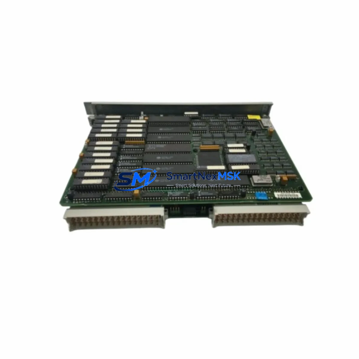
Siemens 6ES5946-3UA23 Retrofit-Ready CPU for SIMATIC S5 Control Systems
The Siemens 6ES5946-3UA23 is a high-performance CPU946 processor module designed for the SIMATIC S5 programmable logic controller platform. As legacy S5 systems continue to operate across manufacturing plants, chemical facilities, power generation sites, and process automation environments worldwide, the demand for verified, drop-in compatible replacement units has never been greater. This module serves as a direct retrofit solution for aging or failed CPU946 installations, enabling engineers to restore full system functionality without redesigning the control architecture or migrating to a new PLC platform.
Whether you are managing an unplanned breakdown or executing a planned control cabinet upgrade, the 6ES5946-3UA23 is engineered to slot into existing SIMATIC S5 racks with minimal reconfiguration. It supports the full S5 instruction set and is compatible with programs developed in STEP 5, preserving your existing ladder logic, function block diagrams, and statement list programs without modification. This makes it an ideal choice for facilities that need to extend the operational life of their S5 infrastructure while deferring a full migration to SIMATIC S7 or TIA Portal-based systems.
Upgrade Compatibility Table
| Parameter | Details |
|---|---|
| Replacement Target | Siemens 6ES5946-3UA21, 6ES5946-3UA11, 6ES5946-3UA13 (CPU946 variants) |
| Compatible Rack | SIMATIC S5 EU900 series central racks (e.g., 6ES5900-0AA11) |
| Backplane Interface | S5 bus connector — direct plug-in, no adapter required |
| Programming Software | STEP 5 v7.x; compatible with PG 740, PG 760, PG 770 programming devices |
| Communication Ports | Serial interface for programming cable (e.g., 6ES5734-1BD20); supports S5-compatible SINEC H1 and L2 via CP modules |
| Power Supply Compatibility | Works with 6ES5955-3LC41, 6ES5955-3LF41, and equivalent S5 PS955 power supply modules |
| I/O Expansion | Supports digital and analog I/O via S5 signal modules (SM321, SM322, SM331, SM332 equivalents) |
| Installation Requirement | DIN rail or rack-mount in EU900 chassis; verify slot addressing and module address switches |
| Retrofit Recommendation | Back up existing STEP 5 program before swap; verify CPU memory card compatibility |
| Warranty | 12-Month Warranty — tested and verified before shipment |
Retrofit Planning for Existing Automation Systems
Successful integration of the 6ES5946-3UA23 into an existing control system requires careful pre-installation planning. Begin by auditing the current rack configuration. The SIMATIC S5 EU900 central rack typically houses the CPU946 in a dedicated slot alongside power supply modules such as the 6ES5955-3LF41 PS955 and interface modules for distributed I/O expansion. Confirm that the rack’s backplane bus is undamaged and that all slot connectors are clean and free of corrosion before installing the replacement CPU.
Next, verify the power budget. The CPU946 draws significant current from the 5 VDC bus, and older power supplies may be operating near their rated capacity. If the existing PS955 power supply shows signs of aging — such as output voltage drift or thermal shutdown — it is advisable to replace it concurrently with the CPU to avoid secondary failures after commissioning. A fresh 6ES5955-3LC41 or equivalent unit will provide stable power headroom for the CPU and any attached signal modules.
Terminal wiring and I/O module addressing must be verified before powering up the new CPU. Digital input modules such as the 6ES5421-8MA11 and digital output modules like the 6ES5441-8MA11 retain their physical wiring, but module address switches must match the address assignments in the STEP 5 program. Analog input modules — for example, the 6ES5466-8MA11 — require range card verification to ensure the signal scaling in the program matches the physical wiring.
Communication continuity is another critical factor. If the existing system uses a 6ES5734-1BD20 programming cable for STEP 5 connectivity, or a CP 5431 communications processor for SINEC L2 or H1 network integration, these modules remain in place and do not require reconfiguration after the CPU swap. However, if the system interfaces with an HMI — such as a SIMATIC OP7, OP17, or a third-party panel connected via the S5 serial interface — verify that the HMI communication parameters (baud rate, station address, protocol type) are correctly set and that the HMI screen tags reference the correct data block addresses in the new CPU’s memory.
For systems that include a 6ES5374-1KH21 memory module or EPROM cartridge containing the user program, confirm that the memory card is compatible with the 6ES5946-3UA23 before insertion. Transfer the program to a PG programming device as a backup prior to any hardware swap. This ensures that the original logic is preserved and can be reloaded if the memory card encounters a read error during initialization.
Downtime Control During System Migration
Minimizing production downtime during a CPU replacement is the primary concern for most maintenance engineers. The 6ES5946-3UA23 is designed to support a rapid swap procedure when the pre-installation checklist has been completed. With the STEP 5 program already backed up to a PG device or laptop running STEP 5 v7.x, the physical replacement can typically be completed within 30 to 60 minutes, depending on rack accessibility and the complexity of the I/O configuration.
Before removing the failed CPU, place the system in a safe state: disable all outputs, notify downstream operators, and engage any mechanical interlocks or safety relays. Remove the memory card from the old CPU and inspect it for damage. Insert the card into the 6ES5946-3UA23, seat the module firmly into the rack slot, and restore power. The CPU will perform a self-test and attempt to load the program from the memory card. Monitor the diagnostic LEDs — STOP, RUN, and BASP — to confirm successful initialization.
If the CPU enters STOP mode after initialization, connect the PG programming device via the 6ES5734-1BD20 cable and use STEP 5 to read the diagnostic buffer. Common causes include memory card incompatibility, incorrect module addressing, or a program block that references I/O addresses not present in the current rack configuration. Resolve each fault systematically before switching to RUN mode. Once the CPU is running, verify all I/O signals against the process values displayed on the HMI or SCADA system, and confirm that all control loops are operating within expected parameters before returning the system to full production.
All units supplied by SMARTNEXMSK are function-tested prior to shipment and covered by a 12-month warranty. In-stock units are dispatched within 1–3 business days, supporting urgent breakdown recovery scenarios with minimal lead time.
Retrofit Support FAQ
Q1: Is the 6ES5946-3UA23 a direct drop-in replacement for the 6ES5946-3UA21?
Yes. The 6ES5946-3UA23 is a later hardware revision of the CPU946 family and is fully backward compatible with the 6ES5946-3UA21 and 6ES5946-3UA11. The backplane connector, rack slot dimensions, and STEP 5 program compatibility are identical. No program modifications are required for a like-for-like swap.
Q2: Do I need to reconfigure the CP communication module after replacing the CPU?
In most cases, no. Communications processors such as the CP 5431 or CP 5511 retain their configuration independently of the CPU. However, if the CPU’s MPI or serial interface address was manually set, verify that the new CPU’s interface parameters match the existing network configuration before going online.
Q3: What wiring changes are required when installing the 6ES5946-3UA23?
No wiring changes are required. The 6ES5946-3UA23 installs directly into the existing EU900 rack slot. All field wiring remains connected to the signal modules (digital I/O, analog I/O) and is unaffected by the CPU replacement. Only the CPU module itself is swapped.
Q4: What does the 12-month warranty cover, and how is the unit tested before shipment?
Every 6ES5946-3UA23 unit is powered on and subjected to a functional self-test prior to dispatch. The 12-month warranty covers hardware defects and functional failures under normal operating conditions. Units that fail within the warranty period are replaced or repaired at no additional cost. Contact sales@smartnexmsk.com for warranty claims and RMA processing.
© 2026 SMARTNEXMSK. All rights reserved.
Original Source: https://smartnexmsk.com
Contact: sales@smartnexmsk.com | +86 18259474341


