SIEMENS 6ES5948-3UR23 Retrofit-Ready CPU for SIMATIC S5 Control Systems
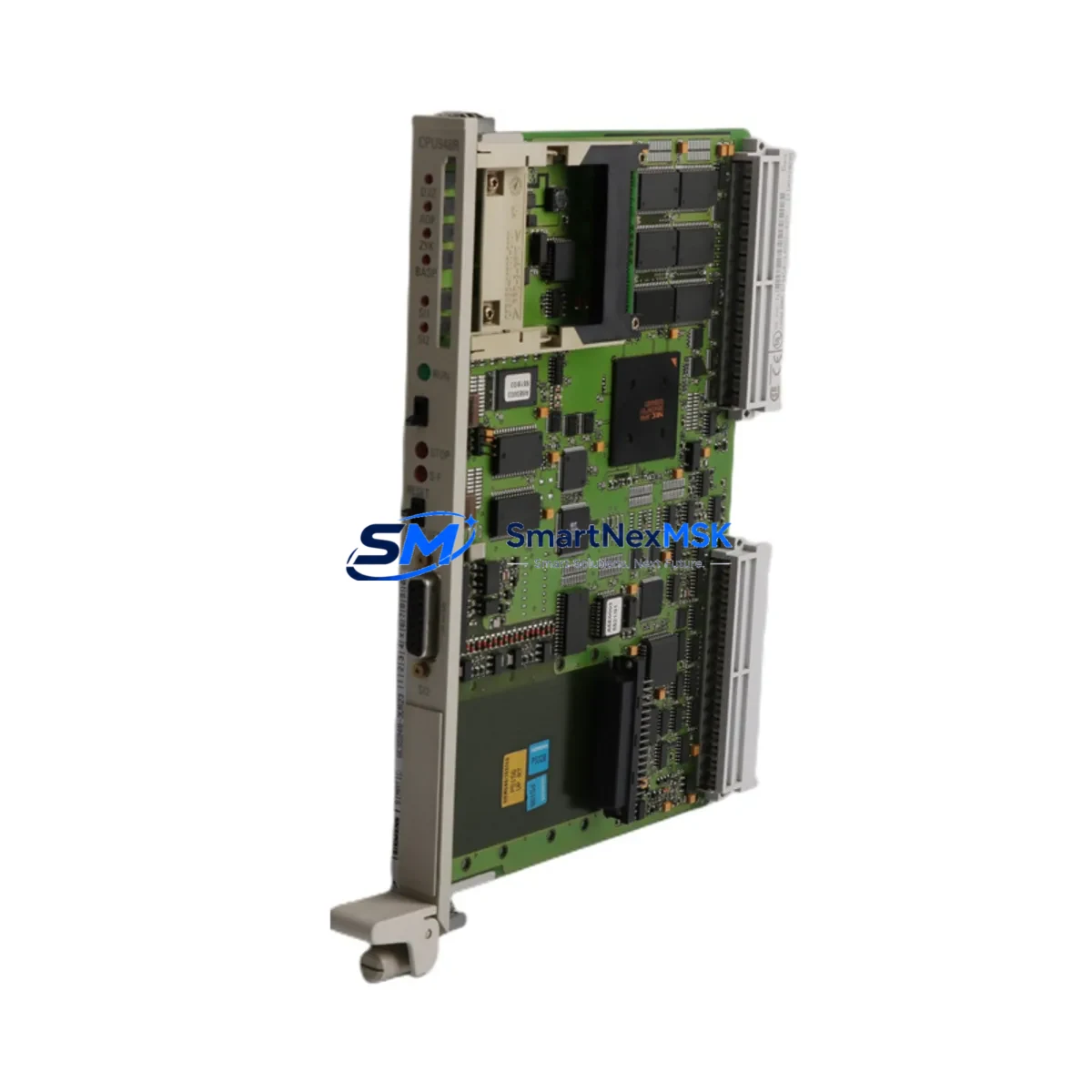
The SIEMENS 6ES5948-3UR23 is a high-performance CPU module engineered for the SIMATIC S5-948 programmable logic controller platform. As legacy S5 systems approach end-of-support milestones and original spare parts become increasingly scarce, the 6ES5948-3UR23 serves as the definitive retrofit-ready replacement for aging control infrastructure across manufacturing, utilities, chemical processing, and heavy industry. Whether you are executing a planned modernization or responding to an unplanned failure, this module delivers the processing power, backplane compatibility, and program memory capacity required to restore and sustain production continuity with minimal disruption.
Sourced from verified industrial supply channels and subject to full functional testing prior to dispatch, every 6ES5948-3UR23 unit shipped by SMARTNEXMSK is backed by a 12-month warranty and supported by pre-sales technical consultation to confirm fit before purchase.
Upgrade Compatibility Table
| Parameter | Detail |
|---|---|
| SKU / Part Number | 6ES5948-3UR23 |
| Compatible Platform | SIMATIC S5-948 (also compatible with S5-945, S5-946 rack configurations where CPU slot accepts 948-series modules) |
| Backplane Interface | S5 bus (parallel backplane); direct slot-in replacement — no adapter required |
| Installation Requirement | Standard S5 rack (e.g., 6ES5700-series subrack); verify slot assignment and module address switches before installation |
| Communication Compatibility | SINEC H1 / L1 via CP modules (e.g., 6ES5734-series); supports existing CP 5430 / CP 5431 configurations |
| Power Supply Compatibility | Works with 6ES5955-series PS modules; confirm 24 VDC / 5 VDC rail capacity before hot-swap |
| Replacement Recommendation | Direct replacement for 6ES5948-3UA11, 6ES5948-3UA21, 6ES5948-3UB21; verify firmware revision compatibility with existing STEP 5 project |
| Commissioning Focus | Module address DIP switches, memory card (6ES5375-series EPROM/RAM), battery backup, and STEP 5 program reload |
| Warranty | 12 months from date of shipment; covers manufacturing defects and functional failure under normal operating conditions |
Retrofit Planning for Existing Automation Systems
A successful retrofit of the 6ES5948-3UR23 into an operating S5 control system requires systematic pre-work across hardware, software, and communications layers. Begin by auditing the existing rack configuration: identify the subrack model (typically a 6ES5700-3AB11 or 6ES5700-3AC11 18-slot rack), document the slot assignments of all installed modules, and photograph the terminal wiring on every I/O module before any removal. Signal modules such as the 6ES5420-series digital input and 6ES5430-series digital output modules must remain in their original slots to preserve the process image table addresses referenced in the STEP 5 program.
Power supply capacity is a critical checkpoint. The 6ES5955-3LC41 or 6ES5955-3LF41 power supply modules must be verified to provide sufficient 5 VDC current for the new CPU plus all installed I/O and communication modules. Overloaded power rails are a leading cause of intermittent faults after CPU replacement. If the existing PS module is marginal, plan its replacement in the same maintenance window.
Communication continuity depends on the CP modules installed in the rack. If the system uses 6ES5734-3BD20 (CP 5430 TF) or 6ES5734-3BE20 (CP 5431 FMS) for PROFIBUS or SINEC L2 connectivity, confirm that the new CPU’s firmware revision supports the existing CP parameter sets. In systems where an IM 308-C interface module manages distributed I/O via PROFIBUS-DP, the DP master configuration stored in the CPU must be re-validated after the swap.
For systems that include an OP 15 or OP 25 operator panel connected via the MPI/PPI port or a dedicated CP link, verify that the HMI screen variable addresses remain consistent with the restored program. Any change in data block numbering or flag addresses during program re-upload will cause HMI display errors that require re-mapping in the panel configuration tool.
Memory card handling is equally important. The 6ES5948-3UR23 uses a 6ES5375-series RAM or EPROM memory submodule to store the user program. If the original memory card is intact and readable, it can often be transferred directly to the replacement CPU, eliminating the need for a full STEP 5 program reload from the programming device. Where the original card is damaged or the program version is uncertain, connect a PG 720 or PG 740 programming device (or a PC running STEP 5 with a 6ES5734-series PC adapter) to upload the current program before powering down the rack.
Finally, analog I/O modules such as the 6ES5460-series analog input and 6ES5470-series analog output modules require re-calibration verification after a CPU swap, particularly in process control applications where scaling parameters are stored in the CPU’s data blocks rather than in the module hardware itself.
Downtime Control During System Migration
Minimizing production downtime during a CPU replacement on a live S5 system demands a structured, time-boxed approach. The recommended sequence is: (1) back up the complete STEP 5 project — including all program blocks (OB, PB, FB, SB), data blocks (DB), and system data — to both the programming device and a secondary storage medium before the maintenance window opens; (2) document the current CPU operating mode (RUN-P, RUN, STOP) and all module status LEDs; (3) set the CPU to STOP mode and remove the memory card before extracting the module from the rack to prevent program corruption; (4) insert the 6ES5948-3UR23, set DIP switches to match the original module address configuration, re-insert the memory card, and power up in STOP mode first to confirm the CPU initializes without hardware faults; (5) perform a controlled RUN transition and monitor the process image for the first 15–30 minutes of operation.
Where process safety requirements prohibit a full system stop, consider a partial migration strategy: use an IM 360 / IM 361 expansion rack pair to isolate non-critical I/O segments, allowing the main CPU rack to be serviced while peripheral I/O continues to hold last-state outputs. This approach is particularly effective in multi-rack S5 configurations where the central processing rack can be briefly isolated without triggering a full plant shutdown.
Pre-staging the replacement 6ES5948-3UR23 on a bench rack with a known-good power supply and a copy of the STEP 5 program — verified to compile and run without errors — reduces the in-field swap time to under 30 minutes in most cases, keeping unplanned downtime within a single shift window.
Retrofit Support FAQ
Q1: Is the 6ES5948-3UR23 a direct drop-in replacement for the 6ES5948-3UA21?
In most cases, yes. Both modules occupy the same CPU slot in the S5 subrack and share the same backplane bus interface. However, firmware revision differences between the -3UA21 and -3UR23 variants may affect compatibility with certain CP module parameter sets and memory card formats. We recommend providing your existing module’s label information and STEP 5 project version when ordering so our technical team can confirm compatibility before shipment.
Q2: What commissioning steps are required after installing the replacement CPU?
After physical installation, verify the module address DIP switch settings match the original configuration, confirm the memory card is correctly seated, check the 5 VDC power rail load, and perform a STOP-to-RUN transition with the programming device connected. Monitor the BASP (enable outputs) signal and the process image update cycle for the first several scans. If the system uses PROFIBUS-DP via an IM 308-C, re-initialize the DP master configuration from the programming device.
Q3: Can the original terminal wiring on I/O modules be left in place during the CPU swap?
Yes. The CPU module does not connect directly to field wiring — all terminal connections are on the signal modules (digital input, digital output, analog input, analog output). As long as the I/O modules remain in their original rack slots and the CPU is in STOP mode during the swap, field wiring does not need to be disturbed. Always confirm the CPU is in STOP and outputs are de-energized before beginning work.
Q4: What does the 12-month warranty cover, and what is the claims process?
The 12-month warranty covers functional failure and manufacturing defects under normal industrial operating conditions (per IEC 61131-2 environmental ratings). It does not cover damage from incorrect installation, overvoltage, or physical impact. To initiate a warranty claim, contact sales@smartnexmsk.com with your order number, a description of the fault, and photos of the module label and installation environment. Replacement or repair is typically processed within 5–7 business days of fault confirmation.
© 2026 SMARTNEXMSK. All rights reserved.
Original Source: https://smartnexmsk.com
Contact: sales@smartnexmsk.com | +86 18259474341


