Siemens 6ES7135-4FB01-0AB0 Retrofit-Ready Analog Output for ET 200S Control Systems
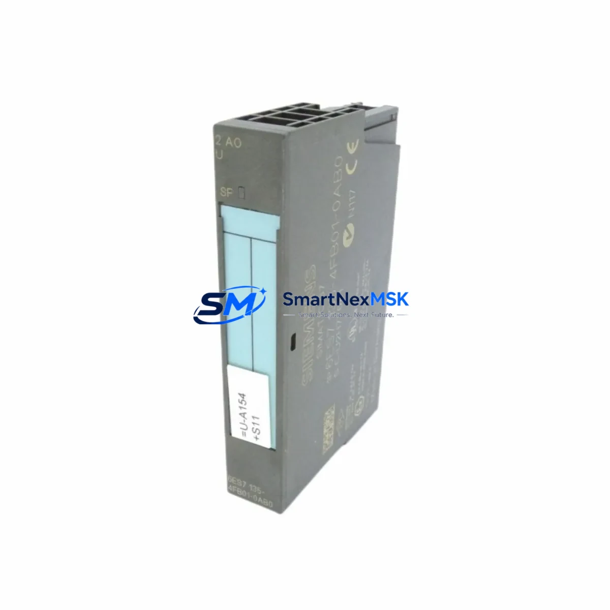
The Siemens 6ES7135-4FB01-0AB0 is a 2-channel analog output module designed for the SIMATIC ET 200S distributed I/O platform. As legacy automation systems approach end-of-life and spare parts become increasingly scarce, this module serves as the definitive retrofit solution for engineers managing aging production lines, control cabinet upgrades, and distributed field I/O expansions. Whether you are replacing a failed unit on a running line or executing a planned migration from an older SIMATIC S5 or early S7-300 architecture, the 6ES7135-4FB01-0AB0 delivers the signal resolution, terminal compatibility, and PROFIBUS DP integration required for a smooth, low-risk transition.
This module outputs 0–10 V or 0–20 mA / 4–20 mA analog signals across two independent channels, making it directly interchangeable with earlier ET 200S analog output variants in most wiring configurations. Before installation, engineers should verify the power budget of the existing ET 200S power module (such as the 6ES7138-4CA01-0AA0) to confirm it can support the additional load. Terminal block wiring should be cross-referenced against the original I/O configuration to avoid signal inversion or ground loop issues, particularly in legacy cabinets where shielding practices may not meet current standards.
Upgrade Compatibility Table
| Parameter | Details |
|---|---|
| SKU / Part Number | 6ES7135-4FB01-0AB0 |
| Platform | SIMATIC ET 200S Distributed I/O |
| Output Channels | 2 × Analog Output (Voltage / Current) |
| Signal Range | 0–10 V, 0–20 mA, 4–20 mA |
| Communication Interface | PROFIBUS DP (via ET 200S IM 151 interface module) |
| Installation | Direct slot insertion on ET 200S terminal module (e.g. 6ES7193-4CD30-0AA0) |
| Replaces / Compatible With | 6ES7135-4FB00-0AB0, earlier ET 200S 2AO variants |
| Controller Compatibility | SIMATIC S7-300, S7-400, S7-1500 (via PROFIBUS DP master) |
| Commissioning Note | Module address must be reassigned in hardware configuration (STEP 7 / TIA Portal) |
| Warranty | 12 Months from date of shipment |
Retrofit Planning for Existing Automation Systems
Successful integration of the 6ES7135-4FB01-0AB0 into an existing control system requires a structured pre-installation review. Begin by auditing the current ET 200S rack layout: confirm the slot position, verify that the corresponding terminal module 6ES7193-4CD30-0AA0 is undamaged, and check that the IM 151-1 interface module (e.g. 6ES7151-1AA06-0AB0) firmware is compatible with the replacement output module. In systems where the ET 200S station communicates over PROFIBUS DP, the DP address of the station must remain unchanged to avoid disrupting the master controller’s GSD-based configuration.
For control cabinets that also house a SIMATIC S7-300 CPU (such as the CPU 315-2 DP or CPU 317-2 DP), the hardware configuration in STEP 7 or TIA Portal must be updated to reflect the new module type. Failure to update the configuration will result in a module mismatch fault and prevent the station from entering RUN mode. If the system uses a CP 342-5 PROFIBUS communication processor for extended DP master functionality, ensure the updated GSD file is loaded and the DP cycle time is sufficient for the analog output refresh rate.
In retrofit scenarios involving older SIMATIC S5 systems being migrated to S7 architecture, the 6ES7135-4FB01-0AB0 is frequently deployed alongside S5-compatible signal converters and updated STEP 7 function blocks to replicate legacy analog scaling logic. Engineers should pay particular attention to the output scaling parameters (gain and offset) configured in the SFB/FB calls, as these directly affect the 4–20 mA loop calibration on field instruments such as control valves and variable-frequency drives.
Where the retrofit involves I/O expansion rather than direct replacement, the 6ES7135-4FB01-0AB0 can be added to an existing ET 200S station provided the power module capacity and the IM 151 slot count allow it. In high-density cabinets, it is common to also install additional ET 200S digital output modules (e.g. 6ES7132-4BD32-0AA0) and analog input modules (e.g. 6ES7134-4FB01-0AB0) in the same upgrade cycle, consolidating the I/O refresh and reducing the number of separate DP stations on the network. All modules should be tested on a bench setup with a PROFIBUS DP master before installation in the live cabinet.
Downtime Control During System Migration
Minimizing production downtime during a module swap or full ET 200S station upgrade requires careful pre-staging. Before the maintenance window opens, prepare the replacement 6ES7135-4FB01-0AB0 with the correct terminal module pre-wired and the hardware configuration downloaded to a spare memory card or laptop running TIA Portal or STEP 7. Where possible, use the SIMATIC S7 PLCSIM environment to simulate the updated hardware configuration and verify that all analog output FB calls execute without faults before going live.
During the swap, place the CPU in STOP mode and use the force table to hold critical output values at safe states before removing the old module. After inserting the replacement module, perform a hardware reset of the ET 200S station and confirm that the IM 151 interface module re-establishes the PROFIBUS DP connection within the expected timeout window. Monitor the diagnostic buffer of the S7 CPU for any remaining module faults and clear them before returning the CPU to RUN mode.
For systems where continuous control is required, consider using a Y-link redundancy module or a hot-standby CPU configuration (available on S7-400H platforms) to allow module replacement without interrupting the control loop. In non-redundant systems, coordinate with the process team to schedule the swap during a planned production break and prepare a manual override procedure for any field devices connected to the analog outputs being replaced. Document the pre-swap and post-swap analog output values to verify that the replacement module is performing within specification before releasing the line.
Retrofit Support FAQ
Q1: Is the 6ES7135-4FB01-0AB0 a direct drop-in replacement for the 6ES7135-4FB00-0AB0?
In most cases, yes. Both modules occupy the same ET 200S slot and use the same terminal module footprint. However, you must update the hardware configuration in STEP 7 or TIA Portal to reference the new order number, as the GSD module identifier differs between revisions. After updating the configuration, perform a full download to the CPU and verify analog output scaling before resuming production.
Q2: What wiring changes are required when replacing an older ET 200S analog output module?
The terminal assignment for voltage and current outputs is consistent across ET 200S 2AO module generations. However, always cross-reference the original wiring diagram against the replacement module’s terminal layout diagram before powering up. Pay particular attention to the shield connection and the sense terminal if 4-wire current output mode is used, as incorrect wiring can damage connected field instruments.
Q3: How do I verify compatibility with my existing PROFIBUS DP network?
The 6ES7135-4FB01-0AB0 communicates exclusively through the ET 200S IM 151 interface module and does not have an independent PROFIBUS address. Compatibility is determined by the IM 151 firmware version and the GSD file loaded in the DP master configuration. Confirm that the IM 151 firmware supports the module revision and that the DP master (S7-300/400/1500 CPU or CP module) has sufficient DP cycle bandwidth to accommodate the analog output refresh without causing watchdog timeouts.
Q4: What does the 12-month warranty cover, and how is the module tested before shipment?
Every 6ES7135-4FB01-0AB0 unit is functionally tested prior to shipment, including analog output signal verification across all configured ranges and PROFIBUS DP communication handshake testing. The 12-month warranty covers manufacturing defects and functional failures under normal operating conditions. Units showing physical damage caused by incorrect installation, overvoltage, or environmental exposure outside the specified operating range are not covered. For warranty claims, contact our technical support team with the module serial number and a description of the fault condition.
© 2026 SMARTNEXMSK. All rights reserved.
Original Source: https://smartnexmsk.com
Contact: sales@smartnexmsk.com | +86 18259474341


