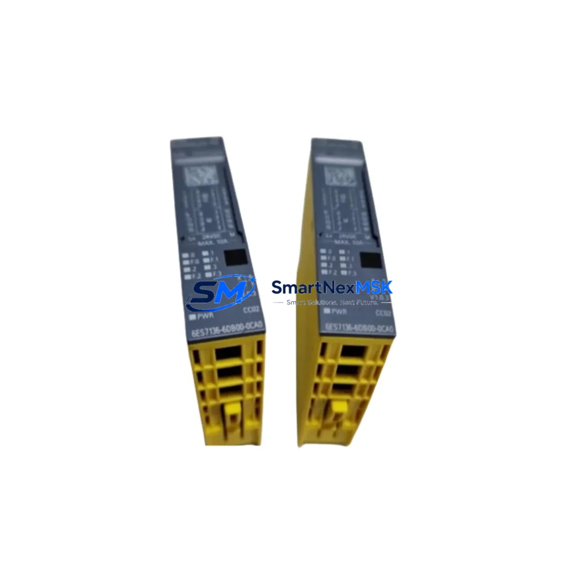
Siemens 6ES7136-6DB00-0CA0 Retrofit-Ready DQ Module for ET 200SP Control Systems
The Siemens 6ES7136-6DB00-0CA0 is a high-density digital output module designed for the ET 200SP distributed I/O system, delivering 8 channels of 24VDC/0.5A output with full PROFINET integration. As legacy S7-300 and early ET 200S installations reach end-of-service milestones, this module has become a primary retrofit target for engineers modernizing distributed control architectures without replacing the entire control cabinet. Its compact form factor, BaseUnit compatibility, and TIA Portal-native configuration make it the preferred drop-in solution for facilities managing phased upgrades across multiple production lines.
When replacing discontinued output modules such as the 6ES7132-4BD32-0AA0 (ET 200S 4DO 24VDC/0.5A) or migrating from older 6ES7132-4BF00-0AA0 variants, the 6ES7136-6DB00-0CA0 requires careful verification of the BaseUnit type. The BU15-P16+A0+2D and BU15-P16+A0+2B BaseUnits are the standard mounting options, and selecting the correct variant determines terminal assignment and potential wiring changes at the field level. Engineers should confirm that existing 24VDC supply rails and load group configurations remain compatible before committing to a direct swap.
Upgrade Compatibility Table
| Parameter | 6ES7136-6DB00-0CA0 (This Module) | Typical Legacy Replacement Target |
|---|---|---|
| Output Channels | 8 × 24VDC / 0.5A | 4–8 channels (varies by model) |
| BaseUnit Compatibility | BU15-P16+A0+2D / BU15-P16+A0+2B | Must verify — not universal |
| Communication Interface | PROFINET via ET 200SP IM (e.g. IM 155-6 PN) | PROFIBUS or PROFINET (check IM type) |
| TIA Portal Support | Yes — V13 SP1 and above | Partial (STEP 7 Classic for older modules) |
| Installation Method | Push-in terminal, tool-free wiring | Screw terminal (rewiring may be required) |
| Diagnostic Capability | Channel-level diagnostics via PROFINET | Limited or module-level only |
| Replacement Recommendation | Direct retrofit with BaseUnit verification | Confirm load group and supply voltage |
| Commissioning Focus | Module address, I/O mapping, HMI tag update | Full re-parameterization may be needed |
| Warranty | 12-Month Warranty — Covered by SMARTNEXMSK | |
Retrofit Planning for Existing Automation Systems
A successful retrofit using the 6ES7136-6DB00-0CA0 begins well before the module arrives on site. The first step is auditing the existing ET 200SP station to confirm the Interface Module type — typically an IM 155-6 PN ST or IM 155-6 PN HF — since the firmware version of the IM governs which module generations are supported. Stations running older IM firmware may require an update via TIA Portal before the new DQ module is recognized on the PROFINET ring.
Terminal wiring is the most time-sensitive task during a live-line retrofit. The 6ES7136-6DB00-0CA0 uses push-in terminals on its BaseUnit, which differs from the screw-terminal design found on many ET 200S predecessors. Field cables terminated with ferrules will connect directly, but bare-wire terminations from older installations may need re-preparation. Confirm that the existing 24VDC power supply — often a SITOP PSU100S 24VDC/10A or equivalent — can sustain the additional inrush current when all 8 output channels switch simultaneously under full load.
For stations that include analog output modules such as the 6ES7135-6GB00-0BA1 (AQ 2×U/I ST) alongside digital outputs, the load group boundary must be re-evaluated. Each load group in an ET 200SP station is defined by a BU-type BaseUnit with an integrated power bus break, and adding or replacing modules can shift the group boundary if the BaseUnit sequence changes. Similarly, if the station includes a 6ES7137-6AA00-0BA0 (CM PTP) communications module for serial protocol bridging, verify that the module slot order in TIA Portal matches the physical rack sequence after the retrofit.
I/O address mapping is another critical checkpoint. In TIA Portal, the hardware configuration must reflect the new module in the correct slot. If the 6ES7136-6DB00-0CA0 replaces a module with a different channel count, the output byte addresses in the PLC program will shift unless the configuration is manually adjusted. Cross-reference the existing symbol table or PLC tag table against the new hardware configuration before downloading. HMI screens built in WinCC Comfort or WinCC Advanced that reference output tags by address rather than symbolic name will require tag updates to maintain correct visualization of valve, motor, or actuator states.
Where the ET 200SP station communicates upstream to a CPU 1515-2 PN or CPU 1516-3 PN/DP controller, the PROFINET device name and IP address of the station must remain unchanged during the module swap. Any accidental reset of the IM’s device name will cause the CPU to lose the I/O connection, triggering a station fault. Label the IM clearly before disconnection and use the “Assign device name” function in TIA Portal to restore the name if needed. For stations with a 6ES7972-0CB20-0XA0 PC adapter or 6GK1571-0BA00-0AA0 USB-to-PROFINET adapter used for on-site programming, confirm the adapter driver version is compatible with the TIA Portal version in use.
Downtime Control During System Migration
Minimizing production downtime during a module swap requires a structured pre-shutdown checklist. Before powering down the ET 200SP station, export the current TIA Portal project and create a timestamped backup of the CPU program, including all data blocks, function blocks, and HMI configurations. If the station supports partial device replacement without a full CPU stop — available on select PN HF Interface Modules — plan the swap during a scheduled maintenance window rather than an emergency shutdown.
During the physical swap, keep the BaseUnit in place if it is compatible with the 6ES7136-6DB00-0CA0. Retaining the BaseUnit preserves all field wiring connections and eliminates the risk of terminal mis-wiring during reassembly. Slide the new module into the BaseUnit, confirm the locking tab engages, and restore power to the station. The IM will automatically detect the new module and report its presence to the CPU via PROFINET. If the hardware configuration in TIA Portal has been pre-loaded with the new module definition, the CPU will transition from STOP to RUN without requiring a full program download — only a hardware configuration download is needed.
Post-swap verification should include a channel-by-channel output test using the TIA Portal “Monitor and Modify” function or the CPU’s force table. Confirm that each of the 8 output channels activates the correct field device — solenoid valve, relay coil, indicator lamp, or motor contactor — before releasing the line back to production. Document the as-built configuration, update the station label, and file the 12-month warranty registration with SMARTNEXMSK to ensure coverage from the commissioning date.
Retrofit Support FAQ
Q1: Is the 6ES7136-6DB00-0CA0 a direct replacement for the 6ES7132-4BD32-0AA0?
Not a plug-and-play swap — the 6ES7132-4BD32-0AA0 belongs to the ET 200S platform and uses a different terminal module and rack system. Migrating to the ET 200SP platform requires replacing the BaseUnit and updating the TIA Portal hardware configuration. However, the field wiring can often be reused if cable lengths and ferrule sizes are compatible with the push-in terminals on the new BaseUnit.
Q2: What commissioning steps are required after installing this module?
After physical installation, download the updated hardware configuration from TIA Portal to the CPU. Verify the module appears online in the device view with no fault LEDs. Run a forced output test on all 8 channels to confirm field device response. Update any HMI tag references if output addresses changed, and perform a final I/O consistency check before returning the system to automatic mode.
Q3: Can this module operate on a PROFIBUS network instead of PROFINET?
No. The 6ES7136-6DB00-0CA0 is designed exclusively for the ET 200SP platform, which communicates via PROFINET. If your existing control system uses PROFIBUS DP, you will need to either replace the Interface Module with a PROFIBUS-compatible IM (such as the IM 155-6 DP) or install a PROFINET-to-PROFIBUS gateway. Contact our technical team to discuss the most cost-effective migration path for your specific network topology.
Q4: What does the 12-month warranty cover, and how is it activated?
The 12-month warranty provided by SMARTNEXMSK covers manufacturing defects, premature failure under normal operating conditions, and DOA (dead-on-arrival) units. Each module undergoes pre-shipment functional testing before dispatch. To activate warranty coverage, retain your purchase invoice and commissioning date record. In the event of a warranty claim, contact sales@smartnexmsk.com with the module serial number, fault description, and proof of purchase. Replacement or repair will be arranged within the warranty period at no additional cost.
© 2026 SMARTNEXMSK. All rights reserved.
Original Source: https://smartnexmsk.com
Contact: sales@smartnexmsk.com | +86 18259474341


