Siemens 6ES7151-1AA06-0AB0 Retrofit-Ready Interface Module for ET200S Control Systems
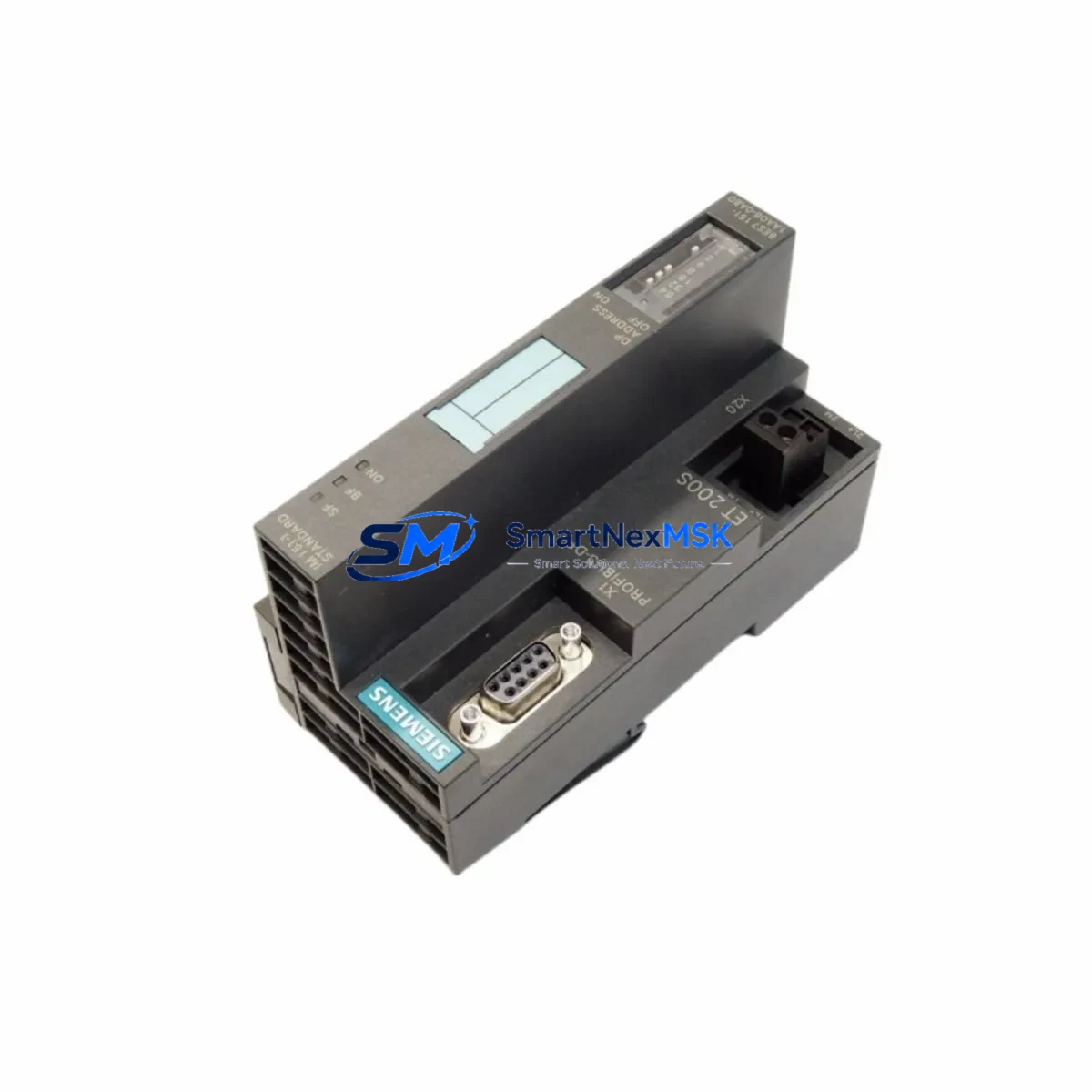
The Siemens 6ES7151-1AA06-0AB0 is a PROFIBUS DP interface module (IM151-1) designed for the ET 200S distributed I/O system. As legacy automation infrastructure ages across manufacturing plants, process facilities, and machine tool lines, this module has become one of the most sought-after retrofit and replacement components in the Siemens S7 ecosystem. Whether you are replacing a failed unit on an active production line, upgrading an aging ET 200S station, or migrating a control cabinet from an older SIMATIC S7-300 architecture, the 6ES7151-1AA06-0AB0 provides a direct, validated path to system continuity with minimal engineering overhead.
This module serves as the communication head for the ET 200S I/O station, establishing the PROFIBUS DP slave connection between the field-level I/O and the upstream controller — typically a SIMATIC S7-300 CPU such as the CPU 315-2 DP or CPU 317-2 DP, or a CP 342-5 communications processor acting as DP master. In retrofit scenarios, engineers must verify that the existing PROFIBUS segment address assigned to the original IM151-1 is preserved in the replacement unit, as address conflicts will prevent the station from being recognized by the DP master during startup. The module’s station address is set via the integrated rotary switch and must match the GSD file configuration loaded in STEP 7 or TIA Portal.
Before installation, confirm that the power budget of the ET 200S rack is within specification. The 6ES7151-1AA06-0AB0 draws its supply from the PM-E power module — typically a 6ES7138-4CA01-0AA0 or 6ES7138-4CB11-0AB0 — and the total current consumption of all installed signal modules (digital input modules such as 6ES7131-4BF00-0AA0, digital output modules such as 6ES7132-4BF00-0AA0, and analog modules such as 6ES7134-4GB11-0AB0 or 6ES7135-4GB01-0AB0) must not exceed the PM-E’s rated output. Failure to audit the power budget before hot-swap replacement is a common cause of post-retrofit instability.
Upgrade Compatibility Table
| Parameter | Details |
|---|---|
| SKU / Part Number | 6ES7151-1AA06-0AB0 |
| Module Type | IM151-1 Interface Module (ET 200S) |
| Communication Protocol | PROFIBUS DP (Slave) |
| Compatible Controllers | SIMATIC S7-300, S7-400 (via DP Master); CP 342-5, CP 443-5 |
| Replaces / Upgrades | 6ES7151-1AA02-0AB0, 6ES7151-1AA03-0AB0, 6ES7151-1AA04-0AB0, 6ES7151-1AA05-0AB0 |
| Backplane Interface | ET 200S internal bus (proprietary Siemens rack) |
| Station Address Setting | Rotary switch (1–99), must match DP master configuration |
| Power Supply | Via PM-E power module on ET 200S rack |
| Installation Requirement | DIN rail mount; ET 200S terminal module required |
| Programming Environment | STEP 7 V5.x / TIA Portal V13 and above |
| Commissioning Note | GSD file must be loaded; station address must be set before power-on |
| Warranty | 12 Months from date of shipment |
Retrofit Planning for Existing Automation Systems
Successful retrofit of the 6ES7151-1AA06-0AB0 into an existing ET 200S station requires a structured pre-installation audit. Begin by documenting the current hardware configuration using STEP 7 HW Config or TIA Portal’s device view, exporting the station configuration to confirm the exact slot assignments of all installed modules. In a typical ET 200S station, the IM151-1 occupies the leftmost slot, followed by the PM-E power module, and then a sequence of signal modules — commonly a mix of 2-wire and 4-wire digital input modules, transistor output modules, and analog input/output modules for process variable acquisition.
Terminal wiring on the ET 200S uses push-in or screw-type terminal modules that are mechanically independent of the electronics modules. This means the signal wiring does not need to be disturbed during an interface module swap — a significant advantage for minimizing downtime. However, engineers should inspect the terminal module (TM-E series) for signs of corrosion or mechanical wear before reinserting the replacement IM151-1.
For systems where the upstream controller is a SIMATIC S7-300 with a CPU 315-2 DP, the PROFIBUS DP network topology must be reviewed. Ensure that the bus termination resistors are correctly placed at both ends of the PROFIBUS segment, and that the baud rate configured in the DP master matches the capability of all slave stations. The 6ES7151-1AA06-0AB0 supports PROFIBUS DP baud rates up to 12 Mbit/s. If the existing network operates at a lower baud rate due to legacy slaves — such as older SIMATIC ET 200M IM153-1 stations or third-party PROFIBUS devices — no baud rate adjustment is required for the replacement module.
In control cabinets where the ET 200S station is co-located with a SIMATIC S7-300 rack, the PROFIBUS cable routing between the CPU’s DP port and the IM151-1 should be inspected for cable integrity, connector seating, and shield grounding. A poorly grounded PROFIBUS shield is a frequent source of intermittent communication faults that are often misdiagnosed as module failures. After physical installation of the replacement 6ES7151-1AA06-0AB0, perform a PROFIBUS diagnostic scan from the DP master to confirm that the station is recognized and that all I/O modules report no faults before resuming production.
Where the retrofit involves migrating from an older IM151-1 variant (such as the 6ES7151-1AA02-0AB0 or 6ES7151-1AA03-0AB0), verify that the GSD file version in the STEP 7 project is compatible with the -1AA06- hardware revision. In most cases, the GSD file is backward compatible, but a hardware configuration download to the CPU may be required to update the module identification data. Always perform this download during a planned maintenance window, as it will cause a brief interruption to the DP communication cycle.
Downtime Control During System Migration
Minimizing unplanned downtime during an ET 200S interface module replacement requires preparation before the maintenance window begins. The most effective approach is to pre-configure the replacement 6ES7151-1AA06-0AB0 offline: set the rotary address switch to match the existing station address, and if the system uses a memory card for parameter storage, prepare the card in advance using a SIMATIC Micro Memory Card programmer.
Before powering down the ET 200S station, capture a full snapshot of the current process state from the HMI — typically a SIMATIC HMI TP or MP panel connected via MPI or PROFINET to the S7-300 CPU. Document all active setpoints, PID parameters, and alarm states. If the control program uses retentive data areas (M, DB) to store process parameters, verify that the CPU’s retentive memory is intact and that a recent program backup exists on the programming device or a network share accessible via STEP 7 or TIA Portal.
During the swap, the PROFIBUS DP master will detect the loss of the slave station and, depending on the CPU’s configured response to DP slave failure (OB86 organization block), may either continue running with the last valid I/O values or transition to STOP mode. For critical processes, configure OB86 to allow the CPU to continue running with substituted values during the brief replacement interval, and ensure that the field devices connected to the ET 200S outputs are in a safe state before removing the IM151-1.
After reinserting the replacement module and restoring power, the DP master will automatically re-establish communication with the slave station within one DP bus cycle. Monitor the CPU’s diagnostic buffer and the ET 200S station’s BF (Bus Fault) LED to confirm successful re-integration. A green RUN LED on the IM151-1 and the absence of BF faults on the DP master confirm that the retrofit is complete and the system has resumed normal operation. Total replacement time for a prepared technician is typically under 15 minutes, keeping production interruption to an absolute minimum.
Retrofit Support FAQ
Q1: Is the 6ES7151-1AA06-0AB0 a direct drop-in replacement for earlier IM151-1 variants such as the 6ES7151-1AA04-0AB0?
A: Yes. The 6ES7151-1AA06-0AB0 is mechanically and electrically compatible with earlier -1AA0x- variants of the IM151-1. The rotary address switch setting and GSD file configuration from the original installation can be reused. A hardware configuration download to the DP master CPU may be required if the project was created with an older GSD file version, but no rewiring or rack modification is needed.
Q2: What commissioning steps are required after installing the replacement module?
A: Set the rotary address switch to match the existing PROFIBUS station address before powering on. After power-on, confirm that the IM151-1’s RUN LED is green and that no BF (Bus Fault) LED is active. From the STEP 7 or TIA Portal programming device, perform a PROFIBUS diagnostic to verify that all I/O modules in the ET 200S station are recognized and fault-free. If any module reports a configuration mismatch, download the hardware configuration from the project to the DP master CPU.
Q3: How do I verify wiring and terminal compatibility before replacing the module?
A: The ET 200S terminal modules (TM-E series) are mechanically independent of the electronics modules, so existing field wiring does not need to be disconnected during the IM151-1 swap. Before installation, inspect the terminal module connector for damage or oxidation. Verify that the PM-E power module is supplying the correct 24 VDC to the rack and that the total current draw of all installed signal modules is within the PM-E’s rated capacity.
Q4: What does the 12-month warranty cover, and is pre-shipment testing performed?
A: Every 6ES7151-1AA06-0AB0 unit is function-tested prior to shipment to verify PROFIBUS communication capability and I/O bus integrity. The 12-month warranty covers manufacturing defects and functional failures under normal operating conditions from the date of shipment. Units that fail within the warranty period are replaced or repaired at no charge. Warranty claims should be initiated by contacting our sales team with the order reference and a description of the observed fault.
© 2026 SMARTNEXMSK. All rights reserved.
Original Source: https://smartnexmsk.com
Contact: sales@smartnexmsk.com | +86 18259474341


