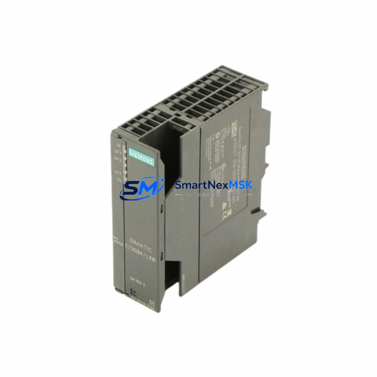
Siemens 6ES7153-2BA10-0XB0 Spare for ET 200M Automation
The Siemens 6ES7153-2BA10-0XB0 is the IM153-2 HF (High Feature) interface module for the SIMATIC ET 200M distributed I/O station, operating over PROFIBUS DP at up to 12 Mbit/s. As a maintenance-ready original spare, this module enables maintenance engineers to restore ET 200M station communication rapidly following an interface module failure — one of the most common causes of unplanned downtime in S7-300 and S7-400 distributed control architectures.
In industrial facilities running continuous processes — chemical plants, automotive assembly lines, water treatment stations, and power distribution substations — a failed IM153-2 HF can take an entire ET 200M rack offline, disabling all associated I/O signals simultaneously. Holding a verified, tested replacement unit of the 6ES7153-2BA10-0XB0 in your spare parts cabinet is the single most effective measure to limit mean time to repair (MTTR) for this failure mode.
This unit ships after full functional verification, including PROFIBUS DP address recognition, backplane communication integrity, and power-on self-test (POST) confirmation. Each unit is covered by a 12-month warranty from date of shipment.
Spare Maintenance Table
| Parameter | Specification |
|---|---|
| Part Number / SKU | 6ES7153-2BA10-0XB0 |
| Module Designation | IM153-2 HF (High Feature) |
| Series / Platform | SIMATIC ET 200M / S7-300 / S7-400 |
| Communication Interface | PROFIBUS DP (Master/Slave), up to 12 Mbit/s |
| Supply Voltage | 24 V DC (via backplane bus) |
| Max. I/O Modules per Station | Up to 8 S7-300 I/O modules |
| Redundancy Support | Yes — Y-Link compatible for redundant PROFIBUS DP |
| Isochronous Mode | Supported |
| Operating Temperature | 0 °C to +60 °C |
| Protection Class | IP20 |
| Mounting | DIN rail, ET 200M rack (UR1/UR2) |
| Country of Origin | Germany |
| Compatibility | SIMATIC S7-300, S7-400, ET 200M UR1/UR2 racks |
| Warranty | 12 Months from shipment date |
| Condition | Original, tested before shipment |
Maintenance Planning for Continuous Operation
When replacing the 6ES7153-2BA10-0XB0 interface module on-site, a disciplined maintenance engineer will not stop at the IM153-2 HF alone. The ET 200M station is a tightly integrated assembly, and a failure event — whether caused by voltage transients, vibration fatigue, or firmware incompatibility — often stresses adjacent components simultaneously.
Begin by inspecting the PS307 24V DC power supply module (e.g., 6ES7307-1BA01-0AA0) that feeds the ET 200M rack. Voltage sags or ripple on the 24 V rail are a leading cause of IM153-2 resets and communication dropouts. Use a calibrated multimeter or power quality analyzer to confirm rail stability before inserting the replacement module.
Next, verify the PROFIBUS DP cable termination and bus connector (e.g., 6ES7972-0BA52-0XA0 bus connector with integrated terminating resistor). A damaged or improperly terminated PROFIBUS segment will cause the new IM153-2 HF to report communication faults immediately after installation, leading to misdiagnosis of the replacement unit. Check both the incoming and outgoing bus connectors at the ET 200M station.
Inspect all SM321 digital input modules and SM322 digital output modules seated in the ET 200M rack. During a station outage, it is good practice to verify that no I/O module has developed a blown fuse or internal fault that was masked by the IM153-2 failure. Similarly, check any installed SM331 or SM332 analog I/O modules for correct channel configuration and signal integrity after power restoration.
If the ET 200M station includes CP342-5 or CP343-5 communication processors for additional PROFIBUS or Industrial Ethernet segments, confirm their firmware versions are compatible with the replacement IM153-2 HF. Firmware mismatches between interface and communication modules are a documented source of intermittent faults in mixed-generation ET 200M installations.
For installations using Y-Link modules (6ES7158-0AD01-0XA0) for redundant PROFIBUS DP, verify that both IM153-2 HF modules in the redundant pair are at the same hardware revision and firmware level. A revision mismatch in a redundant pair can cause switchover failures during the next fault event.
Finally, inspect the terminal blocks and wiring harnesses connected to the I/O modules. Loose or corroded terminals on signal wiring — particularly on 24 V digital inputs and 4–20 mA analog loops — are frequently disturbed during module replacement and should be re-torqued to specification before returning the station to service.
Site Replacement Workflow
Step 1 — Pre-replacement verification: Confirm the PROFIBUS DP station address set on the outgoing IM153-2 HF (rotary switches on the module face). Record the address before removal. The replacement 6ES7153-2BA10-0XB0 must be set to the identical address before installation.
Step 2 — Safe isolation: Place the associated PLC CPU (e.g., CPU 315-2 DP or CPU 317-2 DP) in STOP mode or use the PROFIBUS DP diagnostic function to deactivate the station. Do not hot-swap the IM153-2 HF without confirming the process is in a safe state — the module does not support live insertion in standard ET 200M configurations.
Step 3 — Physical replacement: Remove the PROFIBUS DP bus connectors from the outgoing module. Slide the module off the DIN rail and backplane connector. Insert the replacement 6ES7153-2BA10-0XB0, ensuring the backplane connector seats fully. Reconnect the PROFIBUS DP bus connectors in the correct order (incoming line first, then outgoing).
Step 4 — Address and parameter restore: Set the rotary address switches on the new module to match the recorded station address. If the ET 200M station uses parameter data stored in the IM153-2 HF (rather than the PLC CPU), re-download the station configuration from STEP 7 or TIA Portal using HW Config.
Step 5 — Return to service: Set the CPU back to RUN mode. Monitor the PROFIBUS DP diagnostic LEDs on the IM153-2 HF: the BF (Bus Fault) LED should extinguish within seconds of successful DP communication establishment. Confirm all I/O modules in the rack report no faults in the CPU diagnostic buffer.
This workflow minimizes downtime to under 30 minutes for a prepared maintenance team holding a pre-tested replacement unit, compared to 4–24 hours when sourcing a module reactively after a failure event.
Spare Parts Support FAQ
Q1: Is the 6ES7153-2BA10-0XB0 a direct drop-in replacement for older IM153-2 variants such as 6ES7153-2AA02-0XB0?
The 6ES7153-2BA10-0XB0 (IM153-2 HF) is functionally compatible with earlier IM153-2 variants in standard PROFIBUS DP slave mode. However, the HF variant adds isochronous mode and Y-Link redundancy support not present in earlier versions. Confirm your STEP 7 or TIA Portal HW Config project accepts the new order number before installation. In most cases, a GSD file update and hardware reconfiguration download are sufficient for a seamless transition.
Q2: How do you verify the unit before shipment?
Each 6ES7153-2BA10-0XB0 unit undergoes a power-on self-test, PROFIBUS DP address recognition check, and backplane communication verification on a live ET 200M test rack prior to packaging. A test report is available on request. Units are shipped in anti-static packaging with protective covers on all connectors.
Q3: What is the recommended spare parts stocking strategy for ET 200M installations?
For facilities with 5 or more ET 200M stations on a single PROFIBUS DP segment, we recommend holding a minimum of one IM153-2 HF unit per segment as a cold standby spare. For critical continuous-process applications, a 1:N redundancy ratio (one spare per 3–5 stations) is the industry standard. Pairing the IM153-2 HF spare with a pre-configured PS307 power supply module and a set of PROFIBUS DP bus connectors covers the three most common ET 200M station failure modes.
Q4: What does the 12-month warranty cover?
The 12-month warranty covers manufacturing defects and functional failures under normal operating conditions (per IEC 61131-2 environmental class). It does not cover damage from incorrect installation, overvoltage events, or unauthorized modification. Warranty claims are processed with a replacement-first policy: a verified replacement unit is dispatched before the defective unit is returned, minimizing your downtime exposure.
© 2026 SMARTNEXMSK. All rights reserved.
Original Source: https://smartnexmsk.com
Contact: sales@smartnexmsk.com | +86 18259474341


