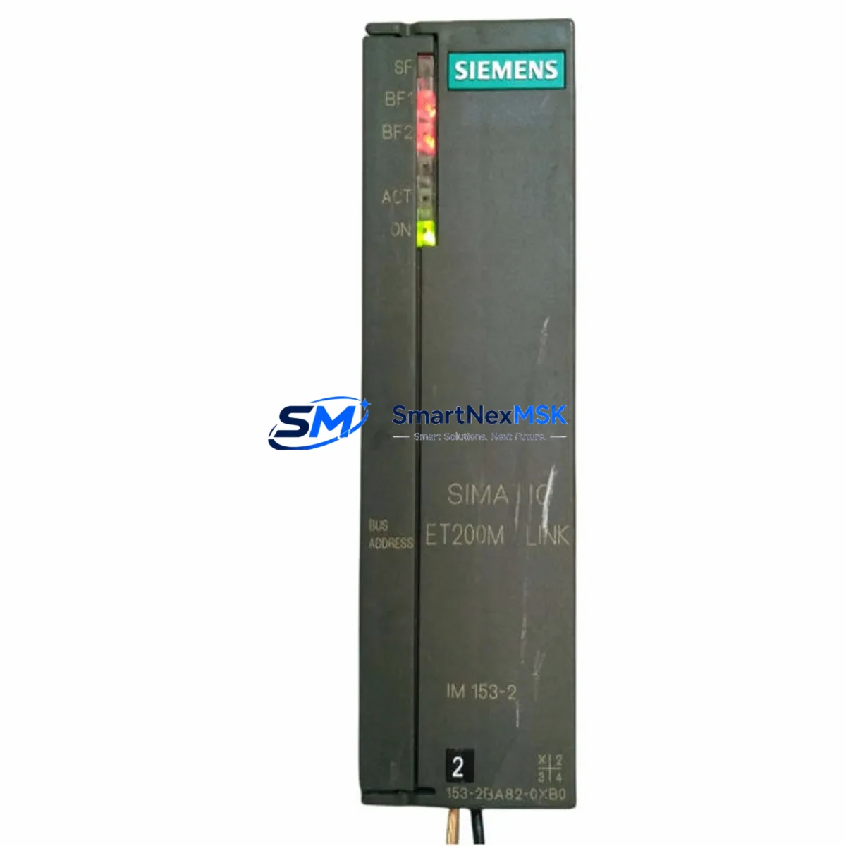
Siemens 6ES7153-2BA82-0XB0 Retrofit-Ready Interface Module for ET 200M Control Systems
The Siemens 6ES7153-2BA82-0XB0 is a high-performance IM153-2 Interface Module designed for the ET 200M distributed I/O station, widely deployed in process automation, manufacturing lines, and legacy SIMATIC S7 control architectures. As original equipment reaches end-of-life or becomes increasingly difficult to source, the 6ES7153-2BA82-0XB0 serves as the definitive retrofit-ready replacement — enabling engineers to restore, upgrade, and future-proof existing control cabinets without redesigning the entire automation system.
This module connects the ET 200M rack to the PROFIBUS DP fieldbus network, acting as the communication gateway between the field-level I/O and the central controller — typically a SIMATIC S7-300 or S7-400 CPU. Its compatibility with both PROFIBUS DP and PROFIBUS PA link configurations makes it a versatile choice for brownfield projects where mixed protocol environments are common. Engineers replacing an older IM153-1 or IM153-2 variant will find that the 6ES7153-2BA82-0XB0 maintains backward compatibility with existing SM300-series signal modules, including digital input modules such as the SM321, digital output modules such as the SM322, and analog I/O modules such as the SM331 and SM332, all of which can remain in place on the existing UR2 or UR2-H backplane rack during the swap.
Before committing to a retrofit, site engineers should verify several critical parameters. Power supply capacity at the ET 200M rack must be confirmed — the PS307 or equivalent 24 VDC power supply must deliver sufficient current for the IM153-2 plus all installed signal modules. Terminal wiring on the PROFIBUS connector (9-pin Sub-D) should be inspected for correct A/B line polarity, bus termination resistor status, and cable shielding continuity. The module’s PROFIBUS station address, set via the address switch on the front panel, must match the GSD file configuration in STEP 7 or TIA Portal to avoid address conflicts on the DP segment. If the existing project was programmed in STEP 7 Classic (v5.x), the hardware configuration must be updated to reflect the new module order number before downloading to the CPU — failure to do so will result in a configuration mismatch fault (SF LED active). For systems using a CP343-1 or CP443-1 communications processor for Ethernet connectivity alongside the PROFIBUS segment, no changes to the CP configuration are typically required, as the IM153-2 operates independently on the DP bus.
HMI screens built on SIMATIC WinCC or WinCC flexible that reference ET 200M I/O tags will continue to function without modification, provided the tag addresses in the symbol table remain unchanged. If the project uses a DP/PA coupler such as the IM157 to extend into PROFIBUS PA instrument loops — for pressure transmitters, flow meters, or valve positioners — the coupler configuration and PA segment topology remain unaffected by the IM153-2 replacement. Commissioning engineers should perform a cold restart of the CPU after module installation and monitor the diagnostic buffer for any residual faults before returning the line to production.
Upgrade Compatibility Table
| Parameter | Details |
|---|---|
| SKU / Order Number | 6ES7153-2BA82-0XB0 |
| Module Type | IM153-2 Interface Module |
| Compatible Station | ET 200M Distributed I/O |
| Fieldbus Interface | PROFIBUS DP (up to 12 Mbit/s) |
| DP/PA Link Support | Yes — via IM157 coupler |
| Backplane / Rack | UR2, UR2-H (standard ET 200M racks) |
| Compatible Signal Modules | SM321, SM322, SM331, SM332, SM334, SM338 |
| Compatible Controllers | SIMATIC S7-300, S7-400, S7-400H (redundant) |
| Programming Software | STEP 7 v5.x, TIA Portal V13+ |
| Power Supply Requirement | 24 VDC (via PS307 or equivalent) |
| Installation | DIN rail, left-most slot of ET 200M rack |
| Replaces / Upgrades From | 6ES7153-2BA00-0XB0, 6ES7153-2BA02-0XB0 |
| Commissioning Tool | STEP 7 HW Config / TIA Portal Device Config |
| Warranty | 12 Months — covers hardware defects and DOA |
Retrofit Planning for Existing Automation Systems
Successful retrofit of the 6ES7153-2BA82-0XB0 into a running production environment requires a structured approach that accounts for every component in the control chain. Begin with a full audit of the existing ET 200M rack: document the slot positions of all installed signal modules, record the current PROFIBUS address, and photograph the terminal wiring on each SM module before any hardware is disturbed. This documentation becomes the reference baseline for post-installation verification.
The IM153-2 occupies the leftmost slot of the ET 200M rack and interfaces directly with the UR2 backplane bus. When the old interface module is removed, inspect the backplane connector pins for corrosion or mechanical damage — a damaged backplane will cause intermittent communication faults that are difficult to diagnose after reassembly. The replacement 6ES7153-2BA82-0XB0 slides into the same slot and locks with the standard module retention mechanism; no tools are required for the mechanical installation itself.
On the PROFIBUS side, the existing bus cable and 9-pin Sub-D connector can typically be reused without modification. Confirm that bus termination is active only at the two physical ends of the DP segment — if this station was previously a segment endpoint, verify that the termination switch on the connector is set correctly. For systems where the ET 200M rack is connected through a repeater module such as the RS485 Repeater to extend cable length or isolate segments, no changes to the repeater configuration are needed.
Inside the control cabinet, the PS307 5A or 10A power supply feeding the ET 200M rack should be load-tested to confirm it can support the full complement of signal modules. Analog modules such as the SM331 8xAI and SM332 4xAO draw more current than digital modules, and a marginal power supply that was adequate for the original configuration may become a reliability risk after years of capacitor aging. If the power supply is more than eight years old, this retrofit is an appropriate time to replace it alongside the interface module.
For facilities running redundant S7-400H systems with a redundant IM153-2 pair, both interface modules should be replaced simultaneously to maintain firmware version consistency. The active/standby switchover behavior depends on both modules running identical firmware, and a version mismatch can cause unexpected failover events during normal operation.
Downtime Control During System Migration
Minimizing production downtime during an ET 200M interface module replacement requires pre-staging all materials and completing as much preparation work as possible while the line is still running. The actual hot-swap window — from removing the old IM153-2 to restoring communication on the new 6ES7153-2BA82-0XB0 — can be completed in under 15 minutes by an experienced engineer when the following steps are pre-completed.
Before the maintenance window opens, download and save the current STEP 7 or TIA Portal project to a local backup. Export the symbol table and hardware configuration as separate files. Confirm that the replacement module’s PROFIBUS address switch is pre-set to match the existing station address — this is the single most common cause of extended downtime during IM153-2 replacements. If the project uses SYNC/FREEZE grouping for coordinated I/O updates, note the group assignments so they can be verified after restart.
During the swap, place the CPU in STOP mode before removing the interface module. This prevents the DP master from generating repeated diagnostic interrupts that can fill the CPU diagnostic buffer and complicate post-restart analysis. After installing the 6ES7153-2BA82-0XB0, perform a power cycle of the ET 200M rack (not the CPU) to allow the new module to initialize its internal firmware and establish the backplane bus connection with the signal modules. Then switch the CPU back to RUN mode and monitor the BF (Bus Fault) LED on the IM153-2 — it should extinguish within two DP bus cycles once the master recognizes the station.
Original program logic in the CPU — including all function blocks, data blocks, organization blocks, and PID control loops — is preserved throughout this process. The IM153-2 replacement does not alter any data in the CPU memory. HMI operator screens will resume normal tag communication automatically once the DP bus is re-established, with no operator intervention required at the WinCC station.
Retrofit Support FAQ
Q: Is the 6ES7153-2BA82-0XB0 a direct drop-in replacement for the 6ES7153-2BA00-0XB0?
A: Yes. The 6ES7153-2BA82-0XB0 is the current production successor to earlier IM153-2 variants including the 6ES7153-2BA00-0XB0 and 6ES7153-2BA02-0XB0. It uses the same rack slot, the same PROFIBUS connector, and is recognized by STEP 7 and TIA Portal with a hardware configuration update. No rewiring of signal modules or backplane changes is required.
Q: Do I need to update my STEP 7 project before installing the new module?
A: Yes. In STEP 7 HW Config or TIA Portal Device Configuration, update the IM153-2 order number to 6ES7153-2BA82-0XB0 and compile the hardware configuration before downloading to the CPU. Running the CPU with a mismatched hardware configuration will result in a module fault (SF LED) and the ET 200M station will not enter data exchange mode.
Q: What does the 12-month warranty cover?
A: The 12-month warranty covers all hardware manufacturing defects and dead-on-arrival (DOA) units from the date of shipment. Each module undergoes functional testing prior to dispatch, including PROFIBUS communication verification and power-on self-test. Warranty claims are processed with priority turnaround to minimize your production impact. Contact sales@smartnexmsk.com to initiate a warranty claim.
Q: Can this module be used in a redundant S7-400H configuration?
A: Yes. The 6ES7153-2BA82-0XB0 supports redundant IM153-2 operation when used in pairs on an ET 200M rack connected to an S7-400H redundant controller. Both modules must run the same firmware version for stable active/standby switchover. Confirm firmware compatibility in TIA Portal before commissioning the redundant pair.
© 2026 SMARTNEXMSK. All rights reserved.
Original Source: https://smartnexmsk.com
Contact: sales@smartnexmsk.com | +86 18259474341


