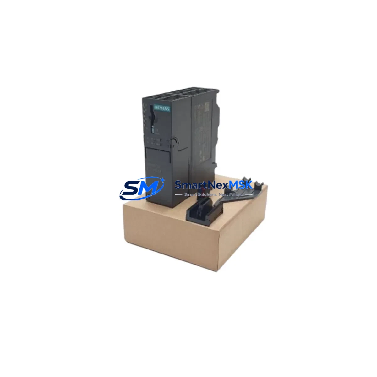
Siemens 6ES7153-4AA01-0XB0 Retrofit-Ready Interface Module for ET 200M Control Systems
The Siemens 6ES7153-4AA01-0XB0 is the IM 153-4 PN IO interface module designed for the ET 200M distributed I/O station. As legacy automation lines face increasing pressure to modernize, this module serves as a critical retrofit component for facilities migrating from older PROFIBUS-based architectures to PROFINET-based control platforms. Whether you are replacing a failed unit in an existing ET 200M rack or planning a phased upgrade of your distributed I/O infrastructure, the 6ES7153-4AA01-0XB0 provides a direct, compatible path forward without requiring full system replacement.
This interface module connects the ET 200M station to a PROFINET IO controller — typically a Siemens S7-300 or S7-400 CPU — via standard RJ45 Ethernet ports. It supports media redundancy (MRP) and isochronous real-time (IRT) communication, making it suitable for high-availability production environments where communication interruptions are not acceptable. For plants still running PROFIBUS DP via an IM 153-1 or IM 153-2 interface module, the 6ES7153-4AA01-0XB0 represents the recommended upgrade path to PROFINET without disturbing the existing SM 300-series signal modules already installed in the backplane.
Upgrade Compatibility Table
| Parameter | Details |
|---|---|
| SKU / Order Number | 6ES7153-4AA01-0XB0 |
| Module Type | IM 153-4 PN IO — Interface Module for ET 200M |
| Communication Protocol | PROFINET IO (RT / IRT), Media Redundancy (MRP) |
| Replaces / Upgrades From | IM 153-1 (6ES7153-1AA03-0XB0), IM 153-2 (6ES7153-2BA02-0XB0) — PROFIBUS DP predecessors |
| Compatible Backplane / Rack | ET 200M IM Rack; supports up to 8 SM 300-series signal modules |
| Compatible Controllers | Siemens S7-300, S7-400, S7-1500 (via proxy), WinAC RTX |
| Installation Interface | DIN rail mount; front connector via ET 200M backplane bus |
| Power Supply Requirement | 24 VDC via PS 307 or PS 305 power supply module |
| Retrofit Wiring Impact | No rewiring of SM signal modules required; only IM slot replacement |
| Commissioning Tool | STEP 7 V5.x / TIA Portal V13+; GSD/GSDML file required |
| Firmware Update | Supported via PROFINET; check firmware compatibility before replacement |
| Warranty | 12-Month Warranty — Covered against manufacturing defects and functional failure |
Retrofit Planning for Existing Automation Systems
Replacing the interface module in an ET 200M station requires careful pre-migration planning to avoid unplanned downtime and configuration errors. Before removing the existing IM 153-1 or IM 153-2, engineers should document the current PROFIBUS DP address, verify the slot assignments of all installed SM 321 digital input modules, SM 322 digital output modules, SM 331 analog input modules, and SM 332 analog output modules, and export the current hardware configuration from STEP 7 or TIA Portal.
The 6ES7153-4AA01-0XB0 uses a GSDML file for PROFINET device identification. This file must be imported into the engineering station before the new IM can be recognized by the IO controller. If the plant is running a Siemens S7-400 CPU 414 or CPU 416 as the PROFINET IO controller, ensure the CPU firmware supports PROFINET IRT before proceeding. For older S7-300 CPUs such as the CPU 315-2 PN/DP or CPU 317-2 PN/DP, standard PROFINET RT is supported and no firmware upgrade is typically required.
During the physical swap, the ET 200M backplane bus connector must be inspected for pin damage. The PS 307 or PS 305 power supply module feeding the rack should be verified to deliver stable 24 VDC within ±5% tolerance. After seating the 6ES7153-4AA01-0XB0, the module address is assigned via the IO controller’s hardware configuration — not via DIP switch as with older PROFIBUS modules — which simplifies address management in multi-station installations.
For plants also upgrading their HMI layer, the migration from a TP 177B or OP 177B operator panel to a newer KTP700 Basic or KTP900 Basic panel can be coordinated in parallel. HMI screen tags referencing ET 200M I/O addresses remain valid as long as the PLC program’s I/O mapping is preserved during the hardware reconfiguration. If the plant uses a CP 343-1 or CP 443-1 communications processor for Ethernet connectivity at the controller level, verify that the PROFINET subnet does not conflict with existing industrial Ethernet segments.
For facilities using a programming cable such as the PC Adapter USB A2 or MPI/PROFIBUS adapter for legacy STEP 7 access, note that TIA Portal commissioning of the 6ES7153-4AA01-0XB0 is performed entirely over Ethernet, eliminating the need for serial programming interfaces during the PROFINET commissioning phase.
Downtime Control During System Migration
Minimizing production interruption during an ET 200M interface module replacement requires a structured cutover plan. The recommended approach is to perform the hardware swap during a scheduled maintenance window, with the PLC program backed up to both the CPU memory card and an offline project archive before any physical work begins. The S7-300 or S7-400 CPU should be placed in STOP mode only after confirming that all field actuators are in a safe state and that the process can tolerate a controlled pause.
Because the 6ES7153-4AA01-0XB0 replaces only the interface module and not the signal modules, the existing field wiring connected to the SM 321, SM 322, SM 331, and SM 332 modules remains undisturbed. This is the primary advantage of an IM-only retrofit: the terminal blocks, cable shields, and I/O channel assignments do not need to be touched, which dramatically reduces the risk of wiring errors during recommissioning.
After the new IM is seated and the PROFINET connection is established, the IO controller will attempt to establish communication with the ET 200M station using the configured device name. The device name must be assigned to the 6ES7153-4AA01-0XB0 using the “Assign Device Name” function in TIA Portal or STEP 7 before the station will come online. Once the device name is confirmed and the IO controller transitions to RUN mode, all SM module channels should be verified against the pre-migration I/O test records to confirm signal integrity before resuming production.
For high-availability installations using media redundancy, the MRP ring topology should be tested after cutover by intentionally disconnecting one PROFINET cable segment and confirming that the ring switches over within the configured watchdog time without triggering a CPU fault. This test validates the redundancy configuration and confirms that the 6ES7153-4AA01-0XB0 is operating correctly within the network topology.
Retrofit Support FAQ
Q1: Is the 6ES7153-4AA01-0XB0 a direct drop-in replacement for the IM 153-2 (6ES7153-2BA02-0XB0)?
The 6ES7153-4AA01-0XB0 is a functional upgrade rather than a pin-compatible drop-in. Both modules occupy the same IM slot in the ET 200M rack and support the same SM signal modules. However, the 6ES7153-4AA01-0XB0 uses PROFINET IO instead of PROFIBUS DP, so the controller-side configuration must be updated in STEP 7 or TIA Portal, and the PROFIBUS cable is replaced with a standard Ethernet patch cable. No field wiring changes are required.
Q2: What commissioning steps are required after installing the 6ES7153-4AA01-0XB0?
After physical installation, import the GSDML file into your engineering project, assign the PROFINET device name using TIA Portal or STEP 7, download the updated hardware configuration to the IO controller, and verify that all SM module channels report correctly in the diagnostic buffer. Perform a full I/O force test before returning the station to automatic operation.
Q3: Can the existing SM 300-series signal modules remain in place during the IM replacement?
Yes. The SM 321, SM 322, SM 331, and SM 332 modules installed in the ET 200M backplane do not need to be removed during the IM swap. Their terminal wiring, channel assignments, and parameter settings are preserved. Only the interface module in the designated IM slot is replaced, which is the primary reason this retrofit approach minimizes downtime and wiring risk.
Q4: What does the 12-month warranty cover for the 6ES7153-4AA01-0XB0?
All units supplied by SMARTNEXMSK are covered by a 12-month warranty against manufacturing defects and functional failure under normal operating conditions. Each module undergoes pre-shipment functional testing before dispatch. In the event of a warranty claim, SMARTNEXMSK provides replacement or repair support. Contact sales@smartnexmsk.com with your order reference and fault description to initiate a warranty case.
© 2026 SMARTNEXMSK. All rights reserved.
Original Source: https://smartnexmsk.com
Contact: sales@smartnexmsk.com | +86 18259474341


