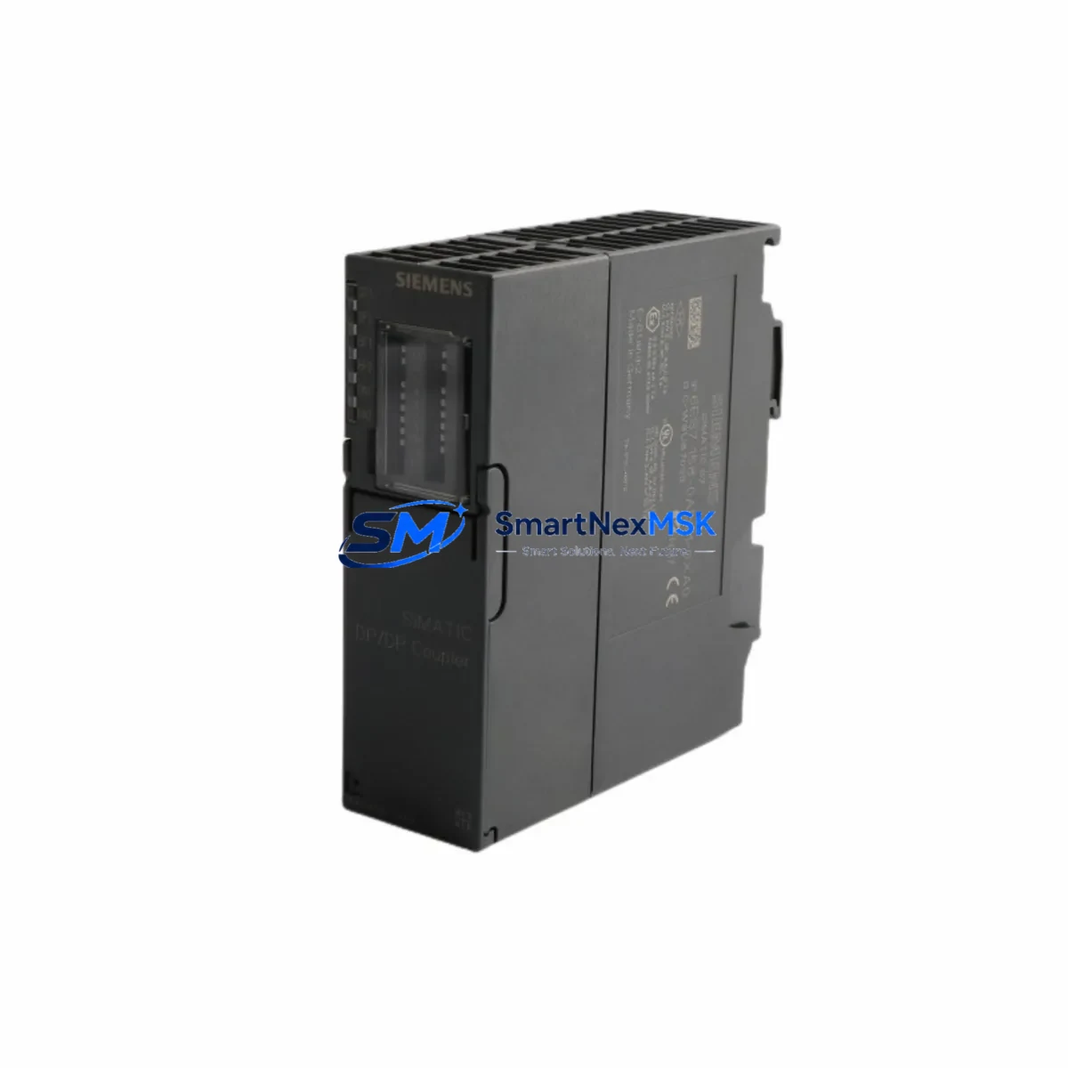
Siemens 6ES7158-0AD01-0XA0 Retrofit-Ready PROFIBUS DP/DP Coupler for S7-300 Control Systems
The Siemens 6ES7158-0AD01-0XA0 is a PROFIBUS DP/DP Coupler designed to interconnect two independent PROFIBUS DP networks, enabling seamless data exchange between master systems without shared bus access. As legacy S7-300 installations approach end-of-life or require expansion, this module serves as a critical bridge component in retrofit projects — allowing engineers to preserve existing field device wiring, retain proven control logic, and extend system service life without a full platform migration.
Whether you are replacing a failed coupler in a running production line, upgrading a distributed I/O segment, or migrating from an older S5-compatible PROFIBUS architecture to a modern S7-300 or S7-400 backbone, the 6ES7158-0AD01-0XA0 provides a verified, drop-in compatible solution. All units supplied by SMARTNEXMSK are tested prior to shipment and covered by a 12-month warranty.
Upgrade Compatibility Table
| Parameter | Details |
|---|---|
| SKU / Part Number | 6ES7158-0AD01-0XA0 |
| Series Compatibility | SIMATIC S7-300, S7-400 (as DP master/slave) |
| Interface | 2 × PROFIBUS DP (9-pin Sub-D), max. 12 Mbit/s |
| Installation | DIN rail mount, no backplane slot required |
| Power Supply | 24 V DC via terminal block (L+ / M) |
| Communication Compatibility | PROFIBUS DP V0 / V1; GSD file available |
| Replaces / Supersedes | 6ES7158-0AA01-0XA0 (earlier revision) |
| Retrofit Recommendation | Direct replacement; verify GSD version and DP address assignment |
| Commissioning Notes | Set DP slave address via rotary switch before power-on; configure in HW Config (STEP 7 or TIA Portal) |
| Warranty | 12 Months — all units tested before shipment |
Retrofit Planning for Existing Automation Systems
Integrating the 6ES7158-0AD01-0XA0 into an existing control architecture requires careful pre-planning across several system layers. Begin by auditing the existing PROFIBUS segment topology: confirm the baud rate on both DP networks (typically 1.5 Mbit/s or 12 Mbit/s in S7-300 installations), verify termination resistor status at both ends of each segment, and document all existing DP slave addresses to avoid conflicts after the coupler is inserted.
On the power supply side, the coupler requires a stable 24 V DC feed — typically sourced from the same Siemens PS 307 or 6EP1334-2BA20 power supply module already serving the control cabinet. Confirm available current capacity before adding the coupler to the rail. If the cabinet is already at capacity, a supplementary Siemens SITOP PSU100S or equivalent 24 V DC power supply should be provisioned.
Terminal wiring for the PROFIBUS connectors should use shielded twisted-pair cable (PROFIBUS standard cable Type A). When replacing an older 6ES7158-0AA01-0XA0 coupler, the existing cable assemblies and Siemens 6ES7972-0BB52-0XA0 PROFIBUS bus connectors can typically be reused without modification, provided cable integrity is verified with a bus analyzer.
In the STEP 7 HW Config or TIA Portal hardware configuration, the coupler appears as a DP slave on the master network. Import the current GSD file for the 6ES7158-0AD01-0XA0 if it is not already present in the hardware catalog. Assign the DP slave address using the rotary switch on the module face — this must match the address configured in the software before the module is powered on. Mismatched addresses are the most common commissioning error and will prevent the coupler from entering data exchange mode.
For installations involving Siemens ET 200M distributed I/O racks or IM 153-2 interface modules on the subordinate PROFIBUS segment, verify that the I/O module configuration in HW Config reflects the actual physical slot assignments. Any changes to the rack layout — such as adding a SM 321 digital input module or a SM 332 analog output module — must be synchronized between the hardware configuration and the PLC program’s I/O addressing before going live.
If the retrofit also involves migrating HMI screens from an older Siemens OP7 or TP 177B panel to a current KTP700 Basic or KTP900 Basic HMI, ensure that all PROFIBUS DP communication links referenced in the HMI project are updated to reflect the new coupler’s slave address and network segment assignment. Communication links that reference the old coupler’s address will generate connection errors at runtime.
Programming cable access during commissioning is typically handled via a Siemens PC Adapter USB A2 or 6GK1571-0BA00-0AA0 MPI/PROFIBUS adapter. Ensure the programming device has the correct STEP 7 or TIA Portal version installed to match the CPU firmware — particularly important when the retrofit involves a CPU 315-2 DP or CPU 317-2 DP that may have received firmware updates since the original project was created.
Downtime Control During System Migration
Minimizing unplanned downtime is the primary operational concern in any retrofit involving a live production system. For the 6ES7158-0AD01-0XA0, the recommended approach is a staged swap: pre-configure the replacement coupler offline, verify the DP slave address setting, and stage the unit in the cabinet before the planned maintenance window.
During the swap window, follow this sequence: (1) place the CPU in STOP mode and document the current program status; (2) de-energize the PROFIBUS segment — do not hot-swap PROFIBUS connectors under power; (3) remove the failed or legacy coupler and install the 6ES7158-0AD01-0XA0; (4) reconnect PROFIBUS cables and verify termination; (5) restore 24 V DC power to the coupler; (6) bring the CPU back to RUN mode and monitor the diagnostic buffer for DP slave status messages.
If the original PLC program uses organization blocks OB86 (rack failure) or OB122 (I/O access error) for fault handling, these blocks will capture any transient errors during the coupler swap and allow the CPU to remain in RUN mode rather than transitioning to STOP — significantly reducing the impact on connected field devices and downstream process control loops.
For systems where even a brief interruption is unacceptable, consider using a Siemens Y-Link (6ES7197-1LB00-0XA0) to maintain parallel PROFIBUS communication during the transition period. This approach allows the new coupler to be validated online before the legacy unit is fully decommissioned.
All units from SMARTNEXMSK are pre-tested and shipped with a functional test report, reducing the risk of receiving a defective unit and eliminating the need for extended bench testing before installation. The 12-month warranty covers any manufacturing defects identified after installation.
Retrofit Support FAQ
Q1: Is the 6ES7158-0AD01-0XA0 a direct replacement for the 6ES7158-0AA01-0XA0?
Yes. The 0AD01 revision supersedes the 0AA01 revision and is fully backward compatible in terms of PROFIBUS DP functionality, physical dimensions, and terminal assignments. No hardware or software changes are required beyond confirming the DP slave address setting matches your existing HW Config.
Q2: What wiring changes are needed when installing this coupler in an existing S7-300 cabinet?
In most cases, no wiring changes are required. The 9-pin Sub-D PROFIBUS connectors and 24 V DC terminal block connections are identical to the previous revision. Reuse existing PROFIBUS cables and connectors after verifying cable shield continuity and connector pin integrity.
Q3: How do I verify compatibility with my current STEP 7 or TIA Portal project?
Download the current GSD file for the 6ES7158-0AD01-0XA0 from the Siemens Industry Online Support portal and import it into your hardware catalog. Compare the module’s I/O data structure with the existing configuration. If the GSD data structure is unchanged from the 0AA01 revision, no program modifications are needed. If differences exist, update the HW Config and perform a full download to the CPU during the maintenance window.
Q4: What does the 12-month warranty cover, and what is the return process?
The 12-month warranty covers all manufacturing defects and functional failures under normal operating conditions. Units that fail within the warranty period are replaced or refunded. Contact SMARTNEXMSK with the order reference and a description of the fault — our technical team will coordinate the return and replacement logistics with minimal delay.
© 2026 SMARTNEXMSK. All rights reserved.
Original Source: https://smartnexmsk.com
Contact: sales@smartnexmsk.com | +86 18259474341


