Siemens 6ES7222-1HF32-0XB0 Maintenance-Ready Spare S7-200 SMART
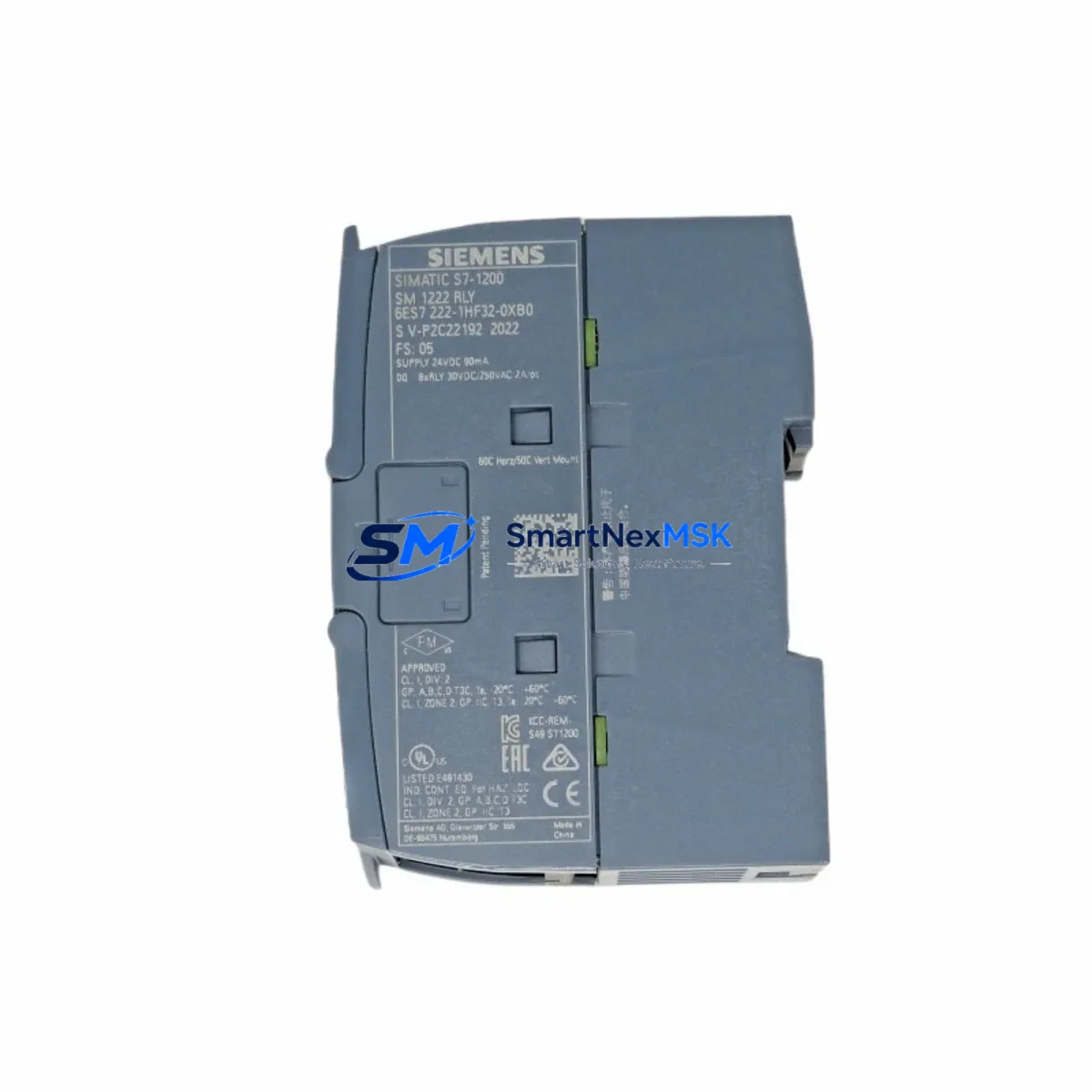
The Siemens 6ES7222-1HF32-0XB0 is an 8-point transistor digital output expansion module designed for the S7-200 SMART series programmable logic controller platform. For maintenance engineers and procurement teams managing aging production lines, this module represents one of the most critical spare parts in any S7-200 SMART-based control cabinet. A failed digital output module can halt conveyor systems, packaging lines, injection molding machines, and HVAC control loops within seconds. Keeping a verified, tested replacement on the shelf is not optional — it is a fundamental part of any responsible maintenance strategy.
The 6ES7222-1HF32-0XB0 provides 8 transistor (sourcing) digital outputs rated at 24 VDC, with a maximum load current of 0.75 A per output and a total group current of 6 A. It connects to the S7-200 SMART CPU via the system expansion bus, occupying one expansion slot on the right side of the CPU module. The module is fully compatible with the S7-200 SMART CPU ST20, CPU ST30, CPU ST40, CPU ST60, and their relay-output counterparts, making it a universal spare across a wide range of installed base configurations.
Spare Maintenance Table
| Parameter | Specification |
|---|---|
| SKU / Part Number | 6ES7222-1HF32-0XB0 |
| Brand / Manufacturer | Siemens |
| Series | S7-200 SMART |
| Module Type | Digital Output (DO) Expansion Module |
| Output Points | 8 × Transistor (Sourcing, PNP) |
| Output Voltage | 24 VDC |
| Max Load Current per Output | 0.75 A |
| Max Group Current | 6 A |
| Logic Supply Voltage | 24 VDC (from CPU bus) |
| Isolation | Optocoupler isolation between field and logic side |
| Connection Type | Removable screw terminal block |
| Expansion Interface | S7-200 SMART system bus connector (right-side expansion) |
| Compatible CPUs | CPU ST20 / ST30 / ST40 / ST60 / SR20 / SR30 / SR40 / SR60 |
| Operating Temperature | 0°C to +55°C |
| Storage Temperature | -40°C to +70°C |
| Dimensions (W×H×D) | Approx. 45 × 100 × 81 mm |
| Weight | Approx. 300 g |
| Installation | DIN rail or panel mount |
| Replacement Compatibility | Direct drop-in replacement for same SKU in S7-200 SMART systems |
| Warranty | 12 Months from date of shipment |
| Shipping Inspection | Function-tested before dispatch |
Maintenance Planning for Continuous Operation
When a 6ES7222-1HF32-0XB0 fails in the field, the fault is rarely isolated to the output module alone. Experienced maintenance engineers know that a thorough inspection of the surrounding control cabinet components is essential before returning the system to production. Begin by verifying the 24 VDC power supply feeding the output module — a Siemens SITOP PSU100S or equivalent DIN-rail power supply should be checked for output voltage stability and ripple, as an under-voltage condition is a common root cause of transistor output burnout.
Next, inspect the terminal block wiring connected to the module’s output terminals. Loose or corroded screw terminals on the removable connector can cause intermittent output faults that are easily misdiagnosed as module failure. If the system uses a Siemens 6ES7288-3AE04-0AA0 (EM AE04 analog input module) or a 6ES7288-2DR08-0AA0 (EM DR08 relay output module) in adjacent expansion slots, verify that the expansion bus connectors between modules are fully seated and free of contamination.
The S7-200 SMART CPU itself — whether a CPU ST40 or CPU SR60 — should be checked for system error LEDs and diagnostic buffer entries using STEP 7-Micro/WIN SMART programming software. Download the current program to confirm that the output address mapping (Q0.0 through Q0.7 for this module, depending on slot position) is correctly assigned and that no force table overrides are masking the fault condition.
For systems that include a Siemens KTP700 Basic HMI panel or a TP700 Comfort panel connected via PROFINET or MPI/RS-485, verify that the HMI alarm screen is not suppressing active output fault alarms. Communication between the CPU and HMI should be confirmed operational before assuming the output module is the sole failure point.
If the control cabinet includes a Siemens 6ES7288-3AM06-0AA0 (EM AM06 analog I/O module) for process variable monitoring, check that analog signal wiring has not been disturbed during the output module replacement procedure. Signal isolation barriers or Siemens SITOP input protection modules installed upstream of the analog inputs should also be inspected for continuity.
For facilities maintaining a structured spare parts inventory, it is recommended to stock at least one 6ES7222-1HF32-0XB0 per production line alongside a Siemens 6ES7288-2DR08-0AA0 relay output module and a 6ES7288-3AE04-0AA0 analog input module. This three-module kit covers the most common expansion module failure scenarios in S7-200 SMART installations and allows maintenance teams to restore full system functionality within a single shift.
Site Replacement Workflow
Replacing the 6ES7222-1HF32-0XB0 on-site is a straightforward procedure when the correct steps are followed in sequence. First, place the CPU in STOP mode using the mode selector switch or via STEP 7-Micro/WIN SMART. Do not remove the expansion module while the CPU is in RUN mode, as this can corrupt the system bus communication and trigger a CPU fault that requires a full program reload.
Power down the 24 VDC supply to the expansion module before disconnecting the terminal block. Label all field wiring connections before removal — a photograph of the terminal block is a reliable reference for reinstallation. Slide the old module off the DIN rail and disconnect the expansion bus connector from the adjacent CPU or module. Install the replacement 6ES7222-1HF32-0XB0 by connecting the expansion bus first, then securing the module to the DIN rail and reconnecting the terminal block.
After reinstallation, restore 24 VDC power and switch the CPU to RUN mode. Monitor the module’s output LEDs and verify that all 8 output channels respond correctly to the program logic. Use the STEP 7-Micro/WIN SMART status monitor to confirm that Q-bit assignments are active and that no system errors are logged in the diagnostic buffer. If the system includes a KTP700 Basic or similar HMI, verify that all output-related HMI screens display correct status before releasing the line to production.
Total replacement time for a prepared maintenance team with a pre-stocked spare is typically 15 to 30 minutes, minimizing production downtime to a single planned maintenance window rather than an extended emergency shutdown.
Spare Parts Support FAQ
Q1: Is the 6ES7222-1HF32-0XB0 a direct replacement for older S7-200 SMART DO modules?
Yes. The 6ES7222-1HF32-0XB0 is the current production part number for the S7-200 SMART 8-point transistor digital output module. It is a direct drop-in replacement for units of the same SKU installed in any S7-200 SMART expansion rack. No firmware update or program modification is required for a like-for-like swap.
Q2: How is the module tested before shipment?
Each unit undergoes functional output verification prior to dispatch. Output channel continuity, isolation integrity, and bus connector condition are checked. A test report is available upon request. All units are shipped in anti-static packaging with protective end caps on the expansion bus connector.
Q3: What is covered under the 12-month warranty?
The 12-month warranty covers manufacturing defects, output channel failure under normal operating conditions, and bus communication faults attributable to the module hardware. It does not cover damage caused by incorrect wiring, overvoltage, or installation in non-compatible systems. Warranty claims are processed within 5 business days of fault confirmation.
Q4: Can this module be used in a mixed expansion configuration with relay output and analog modules?
Yes. The S7-200 SMART expansion bus supports mixed module configurations. The 6ES7222-1HF32-0XB0 can be installed in any expansion slot alongside relay output modules such as the 6ES7288-2DR08-0AA0, analog modules such as the 6ES7288-3AE04-0AA0, and other digital input/output modules, up to the maximum expansion capacity of the connected CPU model.
© 2026 SMARTNEXMSK. All rights reserved.
Original Source: https://smartnexmsk.com
Contact: sales@smartnexmsk.com | +86 18259474341


