Siemens 6ES7223-1PH22-0XA8 Maintenance-Ready Spare S7-200 SMART
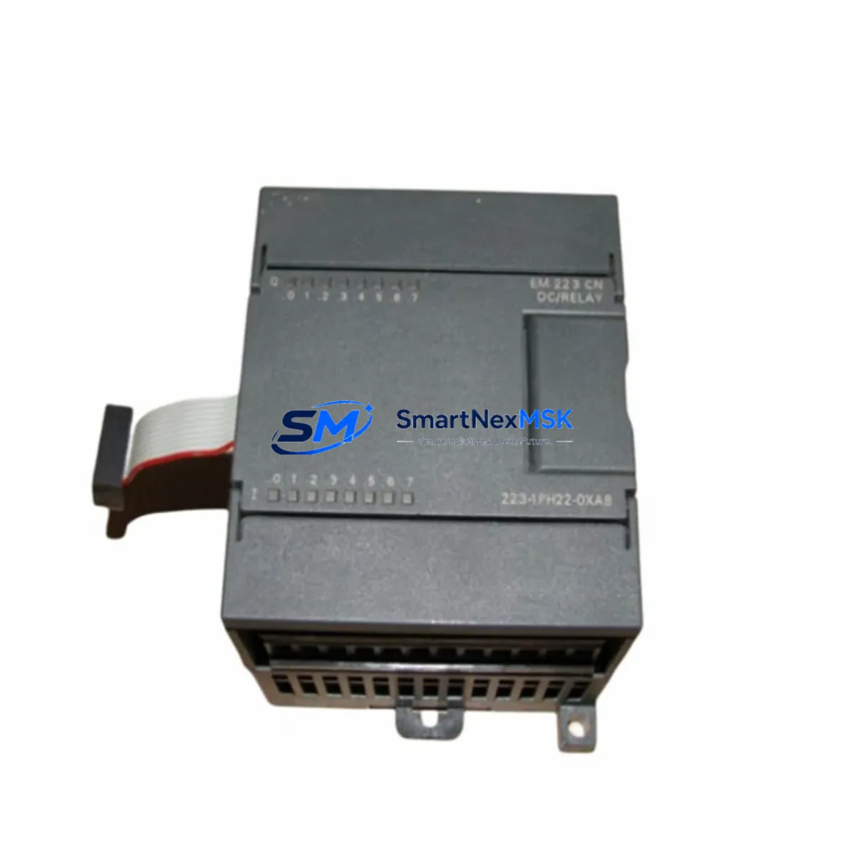
The Siemens 6ES7223-1PH22-0XA8 is an original digital combination expansion module for the S7-200 SMART series, providing 8 digital inputs (24 V DC) and 8 relay digital outputs (2 A per point). For maintenance engineers managing aging S7-200 SMART control systems, this module represents a critical spare that directly impacts production uptime. Unplanned failure of a digital I/O expansion module can halt an entire automated line — having a verified, tested replacement on the shelf is the single most effective strategy for minimizing mean time to repair (MTTR).
This unit ships as an original Siemens component sourced through authorized industrial supply channels, fully tested prior to dispatch, and covered by a 12-month warranty. Whether you are executing a planned annual shutdown, responding to an emergency fault, or building a strategic spare parts inventory for a multi-line facility, the 6ES7223-1PH22-0XA8 is a direct, plug-compatible replacement that requires no firmware changes or parameter re-configuration when substituting a failed unit of the same part number.
Spare Maintenance Table
| Parameter | Specification |
|---|---|
| Part Number / SKU | 6ES7223-1PH22-0XA8 |
| Series Compatibility | Siemens S7-200 SMART (CPU ST20, ST30, ST40, ST60, SR20, SR30, SR40, SR60) |
| Module Type | Digital Combination Expansion Module (8DI / 8DO Relay) |
| Digital Inputs | 8 × 24 V DC, Sink/Source (IEC Type 1) |
| Digital Outputs | 8 × Relay, 2 A / 30 V DC or 250 V AC per point |
| Supply Voltage | 24 V DC (via CPU or external 24 V DC power supply) |
| Power Consumption | ≤ 4 W (internal); 24 V DC bus current ≤ 160 mA |
| Relay Mechanical Life | 10,000,000 operations (no load) |
| Relay Electrical Life | 100,000 operations at rated load |
| Connection Method | Removable screw terminal block |
| Dimensions (W × H × D) | 71.2 mm × 100 mm × 81 mm |
| Operating Temperature | 0 °C to +55 °C (horizontal); 0 °C to +45 °C (vertical) |
| Storage Temperature | −40 °C to +70 °C |
| Protection Rating | IP20 |
| Country of Origin | Germany |
| Certifications | CE, UL, cUL, FM, ATEX (Zone 2) |
| Installation | DIN rail (EN 60715) or panel mount |
| Warranty | 12 Months — tested before shipment |
Maintenance Planning for Continuous Operation
When a 6ES7223-1PH22-0XA8 fails or is flagged during a routine control cabinet inspection, experienced maintenance engineers know that the fault rarely exists in isolation. A relay output module that has reached end-of-life often indicates broader stress on the surrounding electrical circuit. Before returning the system to service, a thorough inspection of the following components is strongly recommended.
Start with the 24 V DC power supply module feeding the S7-200 SMART CPU and expansion bus — voltage ripple or under-voltage events are a leading cause of premature relay contact wear. Verify output voltage is stable within ±1% under full load. Next, inspect the CPU module itself (e.g., CPU ST40 or CPU SR60) for any diagnostic error codes stored in the system buffer; a failing expansion module can generate cascading I/O errors that mask the root cause.
Check the expansion bus connector and flat ribbon cable between the CPU and the first expansion module — oxidation or mechanical stress on this connector is a common but overlooked failure point in older S7-200 SMART installations. While the cabinet is open, inspect all terminal blocks and wiring ferrules on the I/O circuit: loose connections on relay output terminals cause arcing that accelerates contact degradation across the entire output group.
For systems where the relay outputs drive inductive loads such as contactors, solenoid valves, or motor starters, verify that surge suppression components (RC snubbers or varistors) are correctly installed across each load. Missing or failed suppressors dramatically shorten relay contact life. If the system includes a signal isolation module between the PLC output and field devices, confirm isolation integrity with a loop test before re-energizing.
In multi-module expansion racks, also inspect the adjacent analog expansion module (such as the 6ES7235-0KD22-0XA8 or 6ES7231-5PF22-0XA8) and any communication expansion modules (e.g., PROFIBUS DP or Ethernet CP modules) for signs of heat stress or connector corrosion. Finally, review the HMI panel (SMART LINE or KTP series) connected to the CPU — if the HMI has been logging repeated I/O fault alarms, this data provides valuable insight into the failure timeline and helps justify spare parts procurement decisions to management.
Building a minimum viable spare parts kit around the S7-200 SMART platform should include at least one 6ES7223-1PH22-0XA8, one CPU module of the installed type, one 24 V DC power supply, a set of terminal block connectors, and a replacement expansion bus cable. This kit covers the majority of field-replaceable failure scenarios and can restore a stopped line within one shift.
Site Replacement Workflow
Step 1 — Isolate and document. Before removing the failed module, record all wiring connections using photographs or the as-built wiring diagram. Note the module’s slot position in the expansion chain — S7-200 SMART assigns I/O addresses based on physical slot order, so position must be preserved exactly.
Step 2 — Power down safely. De-energize the 24 V DC supply to the expansion bus. Do not hot-swap S7-200 SMART expansion modules; the CPU does not support live insertion and doing so risks corrupting the I/O configuration or damaging the bus interface.
Step 3 — Remove and replace. Disconnect the terminal block (the removable screw terminal design allows wiring to remain intact on the connector). Unclip the failed 6ES7223-1PH22-0XA8 from the DIN rail and disconnect the expansion bus connector. Install the replacement unit in the same slot, reconnect the bus connector, and re-attach the terminal block.
Step 4 — Verify configuration. Power up the system and confirm the CPU recognizes the new module without configuration errors. In STEP 7 Micro/WIN SMART, open the System Block and verify the expansion module table matches the physical installation. No parameter download is required if the replacement is an identical part number.
Step 5 — Functional test. Force each digital input and output point individually using the status monitor in STEP 7 Micro/WIN SMART to confirm correct operation before returning the machine to automatic mode. Document the replacement in the equipment maintenance log with the date, replaced part number, and technician name.
This workflow minimizes downtime to under two hours for a prepared maintenance team and eliminates the risk of configuration errors that can occur when substituting non-identical replacement modules.
Spare Parts Support FAQ
Q1: Is the 6ES7223-1PH22-0XA8 compatible with all S7-200 SMART CPU variants?
Yes. The 6ES7223-1PH22-0XA8 is compatible with all S7-200 SMART CPU modules in the current product range, including the ST20, ST30, ST40, ST60 (transistor output) and SR20, SR30, SR40, SR60 (relay output) variants. The expansion bus protocol is uniform across the S7-200 SMART family. Maximum expansion is limited by the CPU’s total I/O expansion capacity — consult the CPU datasheet for the maximum number of expansion modules supported.
Q2: How is each unit tested before shipment?
Every 6ES7223-1PH22-0XA8 unit undergoes a pre-shipment functional test that verifies all 8 digital input channels, all 8 relay output channels, relay contact continuity, and bus communication integrity. Units that fail any test point are quarantined and not shipped. A test record is retained for each dispatched unit. The 12-month warranty covers defects in materials and workmanship from the date of delivery.
Q3: What is the recommended inventory strategy for this module?
For facilities operating more than three S7-200 SMART systems, we recommend maintaining a minimum of two 6ES7223-1PH22-0XA8 units in the on-site spare parts store. For single-system installations in critical processes (continuous production, utilities, or safety-related applications), one on-site spare is the minimum acceptable level. Modules stored in a dry, temperature-controlled environment within the original packaging retain full functionality indefinitely — there is no shelf-life limitation for this product.
Q4: Can this module replace older S7-200 (non-SMART) expansion modules?
No. The 6ES7223-1PH22-0XA8 is designed exclusively for the S7-200 SMART platform and is not electrically or mechanically compatible with the classic S7-200 series (e.g., EM 223 modules with 6ES7223-1BH22-0XA8 or similar part numbers). If you are maintaining a legacy S7-200 (non-SMART) system, please contact us with your exact CPU part number and we will identify the correct compatible expansion module from our inventory.
© 2026 SMARTNEXMSK. All rights reserved.
Original Source: https://smartnexmsk.com
Contact: sales@smartnexmsk.com | +86 18259474341


