Siemens 6ES7307-1EA00-0AA0 PS-307 5A Maintenance Spare: Spare Parts Replacement & Industrial Downtime Risk Control
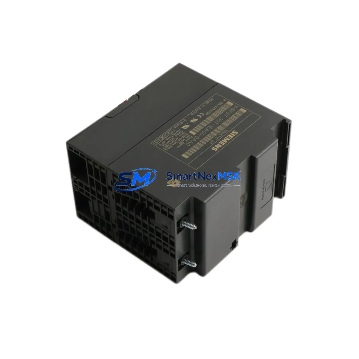
The Siemens 6ES7307-1EA00-0AA0 is the PS 307 5A regulated power supply module designed for the SIMATIC S7-300 programmable logic controller platform. Rated at 24 V DC / 5 A output from a 120/230 V AC input, this module is a foundational component in industrial control cabinets across manufacturing, process automation, and infrastructure sectors. When this power supply fails or degrades, the entire S7-300 rack — including CPU, I/O modules, and communication interfaces — loses its regulated DC bus, resulting in immediate system shutdown and unplanned downtime.
Sourced as an original Siemens spare, the 6ES7307-1EA00-0AA0 is fully compatible with standard S7-300 DIN rail mounting and integrates directly with the S7-300 backplane bus. Each unit is tested before shipment and covered by a 12-month warranty, making it a reliable choice for both emergency replacement and planned maintenance stock.
Spare Maintenance Table
| Parameter | Specification |
|---|---|
| Part Number / SKU | 6ES7307-1EA00-0AA0 |
| Series | SIMATIC S7-300 / PS 307 |
| Module Type | Regulated DC Power Supply |
| Input Voltage | 120 / 230 V AC (auto-ranging) |
| Output Voltage | 24 V DC |
| Output Current | 5 A |
| Output Power | 120 W |
| Mounting | DIN Rail (S7-300 standard profile rail) |
| Dimensions (W×H×D) | 80 × 125 × 120 mm |
| Operating Temperature | 0 °C to +60 °C |
| Protection Class | IP20 |
| Compatibility | SIMATIC S7-300 all CPU variants; compatible with CPU 314, CPU 315-2 DP, CPU 317-2 PN/DP and related expansion racks |
| Origin | Germany |
| Warranty | 12 Months |
| Pre-shipment Test | Yes — output voltage, load regulation, and thermal performance verified |
| Maintenance Recommendation | Inspect every 12–18 months; replace if output ripple exceeds spec or thermal shutdown events are logged |
Maintenance Planning for Continuous Operation
For maintenance engineers managing S7-300-based control systems, the 6ES7307-1EA00-0AA0 sits at the top of the power hierarchy — every downstream component depends on its stable 24 V DC output. A structured maintenance plan should treat this module as a critical spare and address the full power and signal chain simultaneously.
When scheduling a planned inspection or responding to a power-related fault, engineers should evaluate the following components alongside the PS 307 5A:
- CPU modules (e.g., CPU 314C-2 DP, CPU 315-2 PN/DP): Verify firmware version and battery backup status after any power interruption. A power supply replacement is an ideal time to perform a CPU memory backup.
- Digital Input/Output modules (SM 321, SM 322): Check for blown fuses on 24 V DC I/O channels; a degraded power supply often causes intermittent I/O faults before complete failure.
- Analog I/O modules (SM 331, SM 332): Inspect shielding and grounding integrity; unstable supply voltage directly affects analog signal accuracy and calibration.
- IM 360 / IM 361 interface modules: Confirm rack-to-rack communication is stable after power restoration; interface modules are sensitive to voltage transients during power cycling.
- CP 343-1 communication processors: Verify Ethernet or PROFIBUS DP link status after power restoration; communication modules may require a warm restart if the power interruption was abrupt.
- 24 V DC terminal blocks and wiring harnesses: Inspect for loose connections, oxidized terminals, and undersized conductors on the 24 V distribution bus fed by the PS 307.
- Miniature circuit breakers (MCBs) and fuse holders: Check the AC input protection upstream of the PS 307 and the 24 V DC branch circuit protection downstream.
- Surge protection devices (SPDs): Verify that transient voltage suppressors on the AC input and 24 V DC bus are intact, particularly in environments with frequent switching loads.
- SIMATIC HMI panels (e.g., TP700 Comfort, KTP900 Basic): Confirm HMI communication with the CPU is restored and that the panel’s 24 V DC supply is within tolerance after the power module swap.
- Signal isolators and repeaters: For installations with long cable runs or mixed-voltage signal loops, verify that signal isolators powered from the 24 V bus are operating correctly after the replacement.
Maintaining a minimum of one spare 6ES7307-1EA00-0AA0 per control cabinet cluster is a recognized best practice in facilities operating legacy S7-300 systems. Given the age of many installed S7-300 platforms, procurement engineers should also consider stocking the 6ES7307-1KA00-0AA0 (PS 307 10A) for higher-load racks and the 6ES7307-1BA00-0AA0 (PS 307 2A) for auxiliary or remote I/O racks.
Site Replacement Workflow
Replacing the 6ES7307-1EA00-0AA0 on-site is a straightforward procedure when the correct spare is available and the replacement is pre-tested. The following workflow minimizes downtime and ensures system compatibility:
- Isolate and de-energize: Switch off the AC input MCB upstream of the PS 307. Verify zero voltage on the AC terminals using a calibrated multimeter before proceeding.
- Document current configuration: Record the CPU operating mode (RUN/STOP), note any active fault codes on the CPU or HMI, and confirm the CPU memory card is seated. For systems without a memory card, perform a CPU data backup if possible before shutdown.
- Remove the failed module: Disconnect the AC input wiring and 24 V DC output terminals. Slide the PS 307 off the DIN rail. Note the wiring labels for accurate reconnection.
- Install the replacement 6ES7307-1EA00-0AA0: Mount the new module on the DIN rail, reconnect AC input and 24 V DC output terminals per the original wiring diagram. Torque terminal screws to specification (typically 0.5–0.6 N·m).
- Power-on and verify: Energize the AC input. Measure the 24 V DC output under load using a calibrated meter. Confirm the green LED on the PS 307 is steady. Check CPU status and I/O module diagnostics via STEP 7 or TIA Portal online mode.
- Restore operation: Switch the CPU from STOP to RUN. Confirm process values on the HMI are within expected ranges. Log the replacement in the maintenance record with the date, technician ID, and new module serial number.
This replacement procedure is compatible with all S7-300 rack configurations and does not require any firmware changes or parameter re-configuration of the power supply itself. The 6ES7307-1EA00-0AA0 is a direct drop-in replacement for earlier revisions of the same part number, ensuring backward compatibility with existing installations.
Spare Parts Support FAQ
Q1: Is the 6ES7307-1EA00-0AA0 still available as a new original spare, and what is its supply outlook?
Yes. The 6ES7307-1EA00-0AA0 remains available as a new original Siemens spare part. While the S7-300 platform has entered its extended lifecycle phase, power supply modules for this series continue to be stocked to support the large installed base worldwide. We maintain long-term supply capability for this SKU and can advise on alternative sourcing strategies for facilities planning multi-year maintenance contracts.
Q2: How do I verify compatibility before installation?
The 6ES7307-1EA00-0AA0 is compatible with all standard S7-300 racks (UR1, UR2, ER1, ER2) and does not require any configuration changes. Confirm that your rack’s total current draw on the 24 V DC bus does not exceed 5 A. If your system load is higher, the PS 307 10A (6ES7307-1KA00-0AA0) is the recommended upgrade. Physical compatibility is confirmed by the standard S7-300 DIN rail profile and bus connector alignment.
Q3: What pre-shipment testing is performed on each unit?
Every 6ES7307-1EA00-0AA0 unit is tested before shipment for output voltage accuracy (24 V DC ±1%), load regulation under rated 5 A load, and thermal performance. Units are inspected for physical integrity and packaged in anti-static, shock-resistant packaging. A test report is available upon request for quality-critical procurement processes.
Q4: What does the 12-month warranty cover, and what is the claims process?
The 12-month warranty covers manufacturing defects and functional failures under normal operating conditions as specified in the Siemens datasheet. It does not cover damage resulting from incorrect installation, overvoltage events, or operation outside rated parameters. To initiate a warranty claim, contact our technical support team with the order number, installation date, and a description of the fault. Replacement units are dispatched promptly to minimize system downtime.
© 2026 SMARTNEXMSK. All rights reserved.
Original Source: https://smartnexmsk.com
Contact: sales@smartnexmsk.com | +86 18259474341


