Siemens 6ES7313-5BG04-0AB0 Maintenance-Ready Spare for S7-300 Automation
The Siemens 6ES7313-5BG04-0AB0 is a compact CPU 313C module within the SIMATIC S7-300 programmable logic controller family — one of the most widely deployed control platforms in discrete manufacturing, process automation, and utility infrastructure worldwide. As production facilities extend the operational life of legacy S7-300 systems, maintaining a verified, tested spare of the 6ES7313-5BG04-0AB0 CPU is a critical element of any proactive maintenance strategy. Unplanned CPU failure without an available replacement can result in hours or days of unscheduled downtime, with cascading impacts on production throughput, safety interlocks, and regulatory compliance.
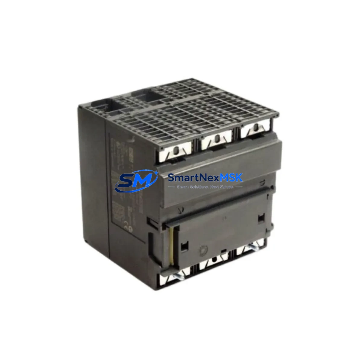
This listing provides an original Siemens 6ES7313-5BG04-0AB0 CPU 313C module, sourced through established industrial supply channels, pre-shipment tested for firmware integrity and I/O functionality, and backed by a 12-month warranty. It is intended for maintenance engineers, reliability teams, and procurement specialists who require a drop-in replacement that preserves full compatibility with existing S7-300 rack configurations, STEP 7 programming environments, and field wiring.
Spare Maintenance Table
| Parameter | Specification |
|---|---|
| Part Number / SKU | 6ES7313-5BG04-0AB0 |
| Product Family | SIMATIC S7-300 |
| Module Type | CPU 313C (Compact CPU with integrated I/O) |
| Integrated Digital I/O | 24 DI / 16 DO |
| Integrated Analog I/O | 4 AI / 2 AO |
| Integrated Counters | 3 × 30 kHz high-speed counters |
| Work Memory | 32 KB |
| Supply Voltage | 24 V DC (via PS 307 or equivalent power supply module) |
| MPI Interface | MPI / DP (integrated) |
| Rack Compatibility | S7-300 standard rail (DIN rail mount) |
| Operating Temperature | 0 °C to +60 °C |
| Protection Class | IP20 |
| Country of Origin | Germany |
| Firmware | V3.3 (compatible with STEP 7 V5.x and TIA Portal via legacy mode) |
| Replacement Compatibility | Direct drop-in for 6ES7313-5BF03-0AB0, 6ES7313-5BE03-0AB0 (verify firmware) |
| Pre-Shipment Test | Power-on, I/O scan, communication port verification |
| Warranty | 12 Months — covers manufacturing defects and functional failure |
Maintenance Planning for Continuous Operation
When a 6ES7313-5BG04-0AB0 CPU requires replacement — whether due to firmware corruption, hardware fault, or scheduled lifecycle refresh — the replacement event should be treated as a full control-cabinet audit opportunity. Maintenance engineers should not limit their inspection to the CPU slot alone.
Begin with the power supply module (typically a Siemens PS 307 5A or 10A, such as the 6ES7307-1EA01-0AA0 or 6ES7307-1KA02-0AA0). A degraded power supply delivering marginal 24 V DC is a common root cause of intermittent CPU resets and memory errors — replacing the CPU without verifying the PSU output under load is a missed diagnostic step. Check ripple voltage and confirm the PSU’s capacitors are within service life.
Next, inspect the signal modules installed in adjacent rack slots. Digital input modules (e.g., SM 321 series such as 6ES7321-1BH02-0AA0) and digital output modules (e.g., SM 322 series such as 6ES7322-1BH01-0AA0) should be checked for blown output transistors, stuck inputs, and terminal block corrosion. Analog input modules (SM 331) and analog output modules (SM 332) should be verified for calibration drift, particularly in temperature-sensitive process environments.
The MPI/PROFIBUS DP communication cable and bus connectors (6ES7972-0BB52-0XA0 or equivalent) are frequently overlooked during CPU swaps. A damaged bus terminator or a connector with a bent pin can prevent the replacement CPU from establishing communication with HMI panels or distributed I/O nodes. Inspect all bus connectors and verify termination resistor settings at both ends of the MPI segment.
If the S7-300 system includes a CP 343-1 Ethernet communication module (e.g., 6GK7343-1EX30-0XE0) for SCADA or MES connectivity, confirm that the IP configuration and connection table are backed up before the CPU swap. The CP module retains its own configuration, but the CPU’s system data block must be reloaded after replacement.
For cabinets with relay output modules or external relay banks, inspect coil voltage ratings and contact wear. Relay modules such as the SM 322 relay variant (6ES7322-1HH01-0AA0) should be tested for contact resistance after extended service. Similarly, terminal blocks and marshalling strips (Phoenix Contact or Weidmüller equivalents) should be checked for loose terminations and insulation degradation, especially in high-vibration or high-humidity environments.
If the installation includes signal isolators or loop-powered transmitter barriers in the analog signal chain, verify isolation integrity and confirm that 4–20 mA loop currents are within specification. A failing isolator can introduce noise that mimics CPU analog I/O faults. Finally, check the SIMATIC memory card or micro memory card (MMC) — the 6ES7953-8LF31-0AA0 or equivalent — for data retention integrity, as MMC failure after a CPU swap can prevent program upload and delay restart.
Site Replacement Workflow
Step 1 — Backup: Before removing the existing 6ES7313-5BG04-0AB0, upload the current program from the CPU to the STEP 7 project on the programming device (PG/PC). Verify the upload is complete and matches the last known-good version in your project archive. If the CPU is non-responsive, retrieve the program from the MMC directly.
Step 2 — Power Down: De-energize the control cabinet following your site’s lockout/tagout (LOTO) procedure. Confirm 24 V DC bus is discharged before handling the CPU module. Label all field wiring connections on the integrated I/O terminal block before disconnection.
Step 3 — Module Swap: Remove the faulty CPU by releasing the DIN rail locking mechanism. Install the replacement 6ES7313-5BG04-0AB0 in the same rack slot. Reconnect the MPI bus connector and all integrated I/O field wiring per the labeled diagram. Insert the MMC with the backed-up program.
Step 4 — Power On and Verify: Restore power and observe the CPU’s LED indicators — RUN (green), STOP (yellow), and BUSF (red). A clean startup should show RUN steady green with no BUSF fault. Use STEP 7 or TIA Portal to go online, verify the program checksum, and confirm all I/O modules are recognized in the hardware configuration.
Step 5 — Functional Test: Execute a controlled I/O test sequence to confirm all digital and analog channels are responding correctly. Verify MPI/DP communication with any connected HMI (e.g., SIMATIC TP or MP panel) and confirm SCADA data is flowing if a CP module is present. Document the replacement in the maintenance log with the new module’s serial number and firmware version.
This workflow minimizes restart time and ensures the replacement CPU is fully validated before returning the system to production — reducing the risk of a secondary fault event during the restart sequence.
Spare Parts Support FAQ
Q1: Is the 6ES7313-5BG04-0AB0 still available as a new original spare, or only as refurbished stock?
We supply original Siemens 6ES7313-5BG04-0AB0 modules from verified industrial supply channels. Each unit undergoes pre-shipment power-on and I/O functional testing. Units are clearly identified by condition grade (new original or tested surplus) in the order confirmation. If you require factory-sealed new stock, please specify at the time of inquiry.
Q2: What is covered under the 12-month warranty?
The 12-month warranty covers manufacturing defects and functional failure under normal operating conditions. It includes free replacement or repair for units that fail to power on, exhibit persistent fault LEDs under correct supply voltage, or show I/O channel failures confirmed by diagnostic testing. Warranty claims require the original order reference and a brief fault description. Physical damage caused by incorrect installation, overvoltage, or environmental exposure is excluded.
Q3: Can this CPU replace an older 6ES7313-5BE03-0AB0 or 6ES7313-5BF03-0AB0 without reprogramming?
In most cases, yes — the 6ES7313-5BG04-0AB0 is backward-compatible with earlier CPU 313C hardware revisions at the program level. However, firmware version differences may require a hardware configuration update in STEP 7 to match the new CPU’s order number. Always verify the hardware configuration object in your STEP 7 project and perform a full I/O test after replacement before returning to production.
Q4: How quickly can the unit be dispatched, and what documentation is provided?
Standard dispatch is within 1–3 business days of order confirmation, subject to stock availability. Each shipment includes a packing list with the module’s serial number, a pre-shipment test record, and a warranty certificate. Express dispatch options are available for emergency breakdown situations — contact our sales team directly to arrange priority handling.
© 2026 SMARTNEXMSK. All rights reserved.
Original Source: https://smartnexmsk.com
Contact: sales@smartnexmsk.com | +86 18259474341


