Siemens 6ES7317-2AJ10-0AB0 Maintenance-Ready Spare S7-300 CPU: Spare Parts Replacement and Industrial Downtime Risk Control
The Siemens 6ES7317-2AJ10-0AB0 is the CPU317-2DP central processing unit for the SIMATIC S7-300 programmable logic controller platform — one of the most widely deployed automation architectures in discrete manufacturing, process control, and utility infrastructure worldwide. As a maintenance-ready original spare, this module is sourced, inspected, and dispatched to support rapid field replacement, minimize unplanned downtime, and sustain the operational continuity of aging or active S7-300 control systems.
For maintenance engineers managing multi-cabinet automation lines, the CPU317-2DP occupies the critical position in the rack: it executes the user program, manages PROFIBUS-DP master communication, coordinates I/O expansion, and interfaces with HMI and SCADA layers. A failure at this node can cascade across the entire production cell. Holding a verified spare on-site — or securing a fast-ship replacement from a qualified supplier — is the single most effective strategy for downtime recovery in S7-300-based systems.
Spare Maintenance Table
| Parameter | Specification |
|---|---|
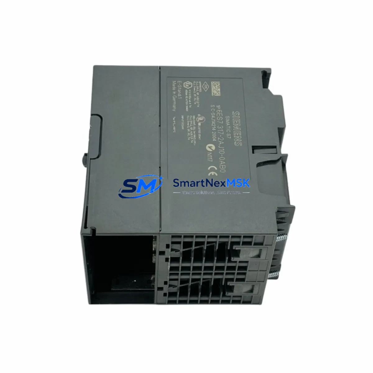
| Part Number / SKU | 6ES7317-2AJ10-0AB0 |
| Module Type | CPU317-2DP — Central Processing Unit with PROFIBUS-DP Master/Slave |
| Platform | SIMATIC S7-300 |
| Work Memory | 512 KB (expandable via memory card) |
| PROFIBUS-DP Interface | Integrated DP master/slave, up to 125 slaves per DP master |
| MPI Interface | Integrated MPI (187.5 kbps default) |
| Supply Voltage | 24 V DC (via PS307 or equivalent power supply module) |
| Rack Compatibility | S7-300 standard rail; slots 2–11 (CPU in slot 2) |
| Operating Temperature | 0 °C to +60 °C (horizontal installation) |
| Protection Class | IP20 |
| Dimensions (W×H×D) | 80 × 125 × 130 mm (approx.) |
| Weight | Approx. 500 g |
| Country of Origin | Germany |
| Compatibility | Direct replacement for 6ES7317-2AJ10-0AB0; compatible with S7-300 racks, SM, FM, CP modules |
| Firmware | Verify firmware version against existing project; update via STEP 7 or TIA Portal if required |
| Warranty | 12 Months — tested before dispatch, full functional verification |
Maintenance Planning for Continuous Operation
When a CPU317-2DP failure is diagnosed or anticipated, a disciplined maintenance engineer does not replace the CPU in isolation. The surrounding electrical environment must be assessed to prevent repeat failures and to confirm the replacement module enters a clean, stable system.
Begin with the power supply module — typically a Siemens PS307 (6ES7307-1BA01-0AA0 or 10A variant) — and verify output voltage stability under load. A degraded power supply is a leading cause of CPU resets and memory corruption; replacing the CPU without addressing a marginal PS307 will result in premature failure of the new module. Check the 24 V DC bus with a calibrated meter before powering the replacement CPU.
Inspect the backplane bus connector on the S7-300 rail. Bent or oxidized bus connector pins cause intermittent communication faults that are frequently misdiagnosed as CPU failures. Replace any bus connectors showing mechanical wear before installing the 6ES7317-2AJ10-0AB0.
Review all digital and analog I/O modules (SM321, SM322, SM331, SM332 series) connected to the rack. A shorted output channel on an SM322 digital output module can draw excessive current and stress the CPU’s internal bus. Use STEP 7 diagnostics or the CPU’s diagnostic buffer to identify any I/O modules reporting hardware faults prior to the CPU failure event.
For systems using PROFIBUS-DP field devices — including ET 200S distributed I/O stations, Siemens SINAMICS or MICROMASTER drives, and third-party DP slaves — verify bus termination resistors at both ends of the DP segment. A missing or failed termination resistor causes bus reflections that can destabilize DP communication and trigger CPU STOP states. Check the DP cable shielding and grounding at the cabinet entry point.
If the system includes CP communication modules (such as CP343-1 for Industrial Ethernet or CP342-5 for additional PROFIBUS-DP masters), confirm that these modules are correctly parameterized after the CPU swap. CP modules store configuration data that may need to be reloaded from the STEP 7 project following a CPU replacement.
For cabinets with signal isolators or analog signal conditioners between field transmitters and SM331 analog input modules, verify loop integrity and 4–20 mA signal levels. Analog signal chain faults are often masked during a CPU failure event and only surface after the CPU is restored to RUN mode.
Check relay output modules and intermediate relay banks (such as Siemens 3RT contactors or Phoenix Contact relay modules) driven by SM322 outputs. Relay coil failures and contact welding are common in high-cycle applications and should be part of any planned maintenance inspection concurrent with a CPU replacement.
Finally, confirm the SIMATIC HMI panel (TP177, MP277, or equivalent) MPI/PROFIBUS connection to the new CPU. After CPU replacement, the HMI may require a connection re-establishment or project download if the CPU’s MPI address has been reset to factory default (address 2). Verify HMI communication before returning the system to production.
Site Replacement Workflow
Step 1 — Backup and documentation. Before removing the existing CPU317-2DP, use STEP 7 or TIA Portal to upload the current program from the CPU (if still accessible) and save the project. Note the CPU’s MPI address, DP master system configuration, and any active memory card contents. Photograph the wiring and front connector layout.
Step 2 — Safe isolation. Switch the CPU to STOP mode. Isolate the 24 V DC supply to the rack via the PS307 circuit breaker. Do not remove the CPU under power. Discharge any residual voltage on the bus before proceeding.
Step 3 — Module removal. Disconnect the MPI/DP cable from the CPU front connector. Remove the front connector (if applicable). Loosen the CPU mounting screws and slide the module off the S7-300 rail. Retain the bus connector for reuse if undamaged.
Step 4 — Replacement installation. Attach the bus connector to the new 6ES7317-2AJ10-0AB0. Slide the module onto the rail and secure the mounting screws. Reconnect the MPI/DP cable. Insert the memory card (if used) with the backed-up program.
Step 5 — Download and commissioning. Restore power. Set the CPU to STOP. Download the project from STEP 7 or TIA Portal. Verify DP master configuration and I/O addressing. Switch to RUN mode and confirm all I/O modules report OK status in the diagnostic buffer. Verify HMI communication and SCADA connectivity before releasing the system to operations.
This workflow supports a target replacement time of under 60 minutes for a prepared maintenance team, significantly reducing mean time to repair (MTTR) compared to unplanned emergency sourcing scenarios.
Spare Parts Support FAQ
Q1: Is the 6ES7317-2AJ10-0AB0 a direct drop-in replacement for my existing CPU317-2DP?
Yes, provided the hardware revision and firmware version are compatible with your existing STEP 7 project. We recommend verifying the firmware version of the replacement module against your project requirements before installation. If a firmware update is needed, this can be performed via STEP 7 using a PC adapter or MPI/USB cable. Contact our technical team with your project details for pre-shipment firmware verification.
Q2: How is the module tested before dispatch?
Each 6ES7317-2AJ10-0AB0 unit undergoes functional power-on testing and visual inspection prior to shipment. Modules are verified for correct LED status indication, MPI communication response, and absence of hardware fault codes. Units are packed in anti-static packaging with protective foam inserts to prevent transit damage. A 12-month warranty is included from the date of dispatch.
Q3: Can you support long-term or scheduled spare parts procurement for S7-300 systems?
Yes. We support both emergency single-unit orders and planned bulk procurement for maintenance departments managing multiple S7-300 installations. For facilities with lifecycle extension programs on legacy S7-300 systems, we recommend establishing a standing spare parts agreement covering CPU modules, power supply modules, and key I/O modules to eliminate sourcing delays during planned shutdowns or unplanned failures.
Q4: What is the warranty coverage and return policy?
All modules are covered by a 12-month warranty from the date of shipment. If a module exhibits a functional defect within the warranty period under normal operating conditions, we will provide a replacement or full refund. Warranty claims require a description of the fault condition and, where possible, the CPU diagnostic buffer log. Modules damaged by incorrect installation, overvoltage, or environmental conditions outside the specified operating range are not covered under warranty.
© 2026 SMARTNEXMSK. All rights reserved.
Original Source: https://smartnexmsk.com
Contact: sales@smartnexmsk.com | +86 18259474341


