Siemens 6ES7317-2AK14-0AB0 Retrofit-Ready CPU for S7-300 Control Systems
The Siemens 6ES7317-2AK14-0AB0 (CPU317-2 DP) is a high-performance central processing unit designed for the SIMATIC S7-300 programmable logic controller platform. As legacy S7-300 installations approach end-of-life and spare parts become increasingly scarce, this module serves as the definitive retrofit-ready replacement for aging CPU315-2 DP, CPU316-2 DP, and earlier CPU317 variants operating in continuous production environments. Whether you are managing a planned system upgrade, an emergency breakdown replacement, or a phased control cabinet modernization, the 6ES7317-2AK14-0AB0 provides the processing headroom, communication flexibility, and backward compatibility required to restore and extend operational continuity with minimal disruption.
This CPU module supports PROFIBUS-DP master/slave communication, enabling seamless integration with existing distributed I/O networks built around ET 200M, ET 200S, and ET 200SP remote I/O stations. Its 512 KB working memory and extended instruction set make it fully capable of executing complex ladder logic, function block diagrams, and structured text programs previously compiled for earlier S7-300 CPU generations. Engineers undertaking a retrofit will find that existing STEP 7 projects compiled under SIMATIC Manager or TIA Portal can be adapted with minimal rework, preserving years of validated control logic investment.
Upgrade Compatibility Table
| Parameter | Details |
|---|---|
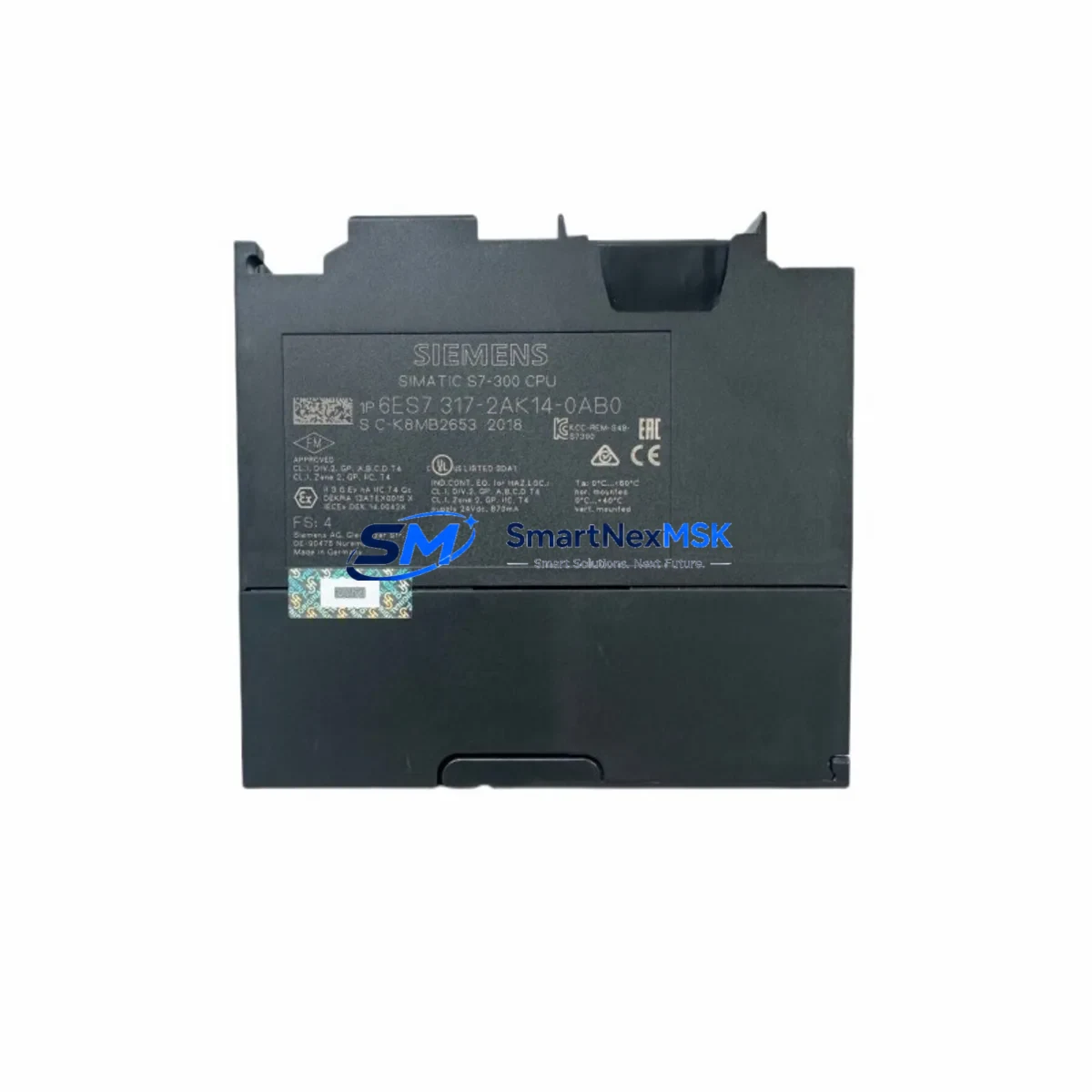
| SKU / Order Number | 6ES7317-2AK14-0AB0 |
| Module Designation | CPU317-2 DP |
| Compatible Platform | SIMATIC S7-300 |
| Replaces | 6ES7315-2AG10-0AB0, 6ES7316-2AG00-0AB0, 6ES7317-2AK13-0AB0 |
| Backplane Interface | S7-300 standard rail, slots 2–11 |
| Communication Ports | MPI/DP (X1), PROFIBUS-DP (X2) |
| Working Memory | 512 KB (program + data) |
| Power Supply Compatibility | PS307 (2A / 5A / 10A), PS305 24VDC |
| Programming Software | STEP 7 V5.5+, TIA Portal V13+ |
| Firmware | V3.3 and above |
| Installation Requirement | DIN rail mount, standard S7-300 rack |
| Commissioning Tool | SIMATIC Manager, TIA Portal, PG/PC cable (MPI or USB-MPI adapter) |
| Warranty | 12 Months — covers manufacturing defects and functional failure under normal operating conditions |
Retrofit Planning for Existing Automation Systems
A successful retrofit of the 6ES7317-2AK14-0AB0 into an existing S7-300 control cabinet begins with a thorough pre-replacement audit. Engineers should first verify that the installed power supply module — typically a Siemens PS307 5A or PS307 10A — can sustain the current draw of the new CPU alongside all installed signal modules. The S7-300 backplane bus current budget must account for all populated slots, including digital input modules such as the SM321 DI 32×DC24V, digital output modules like the SM322 DO 32×DC24V/0.5A, and any analog I/O modules in the rack.
Before physically swapping the CPU, document all existing terminal wiring on the front connectors of each signal module. The S7-300 front connector system allows modules to be replaced without rewiring, provided the connectors are retained and reinserted into the replacement module — a significant advantage during time-critical retrofits. Confirm that the rack slot assignment and module address configuration in the hardware configuration (HW Config) match the physical installation. Any mismatch between the configured and actual slot addresses will generate a hardware fault on startup and prevent the CPU from entering RUN mode.
For systems using PROFIBUS-DP distributed I/O, verify the DP network topology and station addresses assigned to each remote I/O node. The 6ES7317-2AK14-0AB0 supports up to 124 DP slaves on its integrated DP port (X2), making it compatible with large-scale distributed architectures involving multiple ET 200M or ET 200S stations. Confirm that the DP bus termination resistors are correctly placed at both ends of the cable segment, and that the baud rate setting in the hardware configuration matches the physical network — typically 1.5 Mbit/s or 12 Mbit/s for high-speed applications.
If the existing system includes an HMI panel — such as a Siemens TP700 Comfort or KTP900 Basic — connected via MPI or PROFIBUS, verify that the HMI project’s PLC connection settings reference the correct CPU address and communication interface. After the CPU swap, re-establish the HMI connection and perform a full screen navigation test to confirm that all data tags, alarm messages, and trend displays are reading correctly from the new CPU. In systems where the HMI communicates via Ethernet using the S7 protocol, ensure that the CPU’s IP address and subnet mask are correctly configured in TIA Portal and match the HMI connection parameters.
For installations that include a CP343-1 or CP343-1 Advanced Ethernet communication processor, verify that the CP module’s configuration is retained in the hardware project and that its IP settings are consistent with the plant network. Similarly, if a CP342-5 PROFIBUS communication processor is installed for additional DP master functionality, confirm its GSD file is correctly integrated into the hardware configuration before downloading to the new CPU.
Downtime Control During System Migration
Minimizing unplanned downtime during a CPU replacement is the primary operational concern for any maintenance team. The recommended approach is to perform a full backup of the existing CPU’s program and data blocks using SIMATIC Manager or TIA Portal before any hardware is disturbed. Upload the complete project — including all Organization Blocks (OB1, OB35, OB100), Function Blocks, Data Blocks, and System Function Blocks — to a programming device and verify the backup is complete and error-free.
Where production schedules permit, plan the physical swap during a scheduled maintenance window or shift changeover. Power down the rack using the PS307 power supply switch, remove the existing CPU from slot 2, and insert the 6ES7317-2AK14-0AB0 into the same slot. Reconnect the MPI/DP cable to port X1 and the PROFIBUS-DP cable to port X2. Power the rack back on and observe the CPU’s LED indicators: the SF (System Fault) LED should extinguish within the startup sequence, and the RUN LED should illuminate once the program download is complete and the CPU transitions to RUN mode.
Download the backed-up project to the new CPU using a PC Adapter USB A2 or compatible MPI programming cable. After the download, perform a warm restart and monitor the diagnostic buffer for any configuration mismatches or I/O access errors. Confirm that all PROFIBUS-DP slaves have established communication by checking the DP slave status in the diagnostic view. Once all I/O modules report OK status and the process values are reading correctly, the system is ready to resume production. The entire swap procedure, when well-prepared, can typically be completed within 30 to 90 minutes, keeping unplanned downtime to an absolute minimum.
Retrofit Support FAQ
Q1: Is the 6ES7317-2AK14-0AB0 a direct drop-in replacement for the CPU315-2 DP (6ES7315-2AG10-0AB0)?
A: In most cases, yes. The 6ES7317-2AK14-0AB0 occupies the same slot position on the S7-300 rack and uses the same backplane interface. However, the hardware configuration in STEP 7 or TIA Portal must be updated to reflect the new CPU type before downloading the program. The existing program logic is generally compatible, but engineers should review any CPU-specific system functions (SFCs) that may differ between firmware versions.
Q2: What wiring changes are required when replacing the old CPU?
A: No signal wiring changes are required on the I/O modules, as the S7-300 front connector system is retained independently of the CPU. The only connections to verify are the MPI/DP cable on port X1 and the PROFIBUS-DP cable on port X2. Confirm that the bus connector plugs are firmly seated and that termination resistors are correctly set at the network endpoints.
Q3: How is compatibility with the existing PROFIBUS-DP network verified before commissioning?
A: After downloading the hardware configuration and program, use the SIMATIC Manager diagnostic view or TIA Portal’s online device view to check the DP slave status. Each slave should report a green OK status. If any slave shows a fault, verify the station address, GSD file version, and baud rate settings in the hardware configuration match the physical device settings.
Q4: What does the 12-month warranty cover, and how is it claimed?
A: The 12-month warranty covers manufacturing defects and functional failures under normal operating conditions, including CPU startup failures, communication port faults, and memory errors not caused by external electrical damage. To initiate a warranty claim, contact our support team with the order number, a description of the fault symptom, and the CPU’s diagnostic buffer export. Replacement or repair will be arranged promptly to minimize your system downtime.
© 2026 SMARTNEXMSK. All rights reserved.
Original Source: https://smartnexmsk.com
Contact: sales@smartnexmsk.com | +86 18259474341


