Siemens 6ES7321-1BL00-0AA0 Spare for S7-300 Automation: Minimizing Downtime with Maintenance-Ready Digital Input Replacement
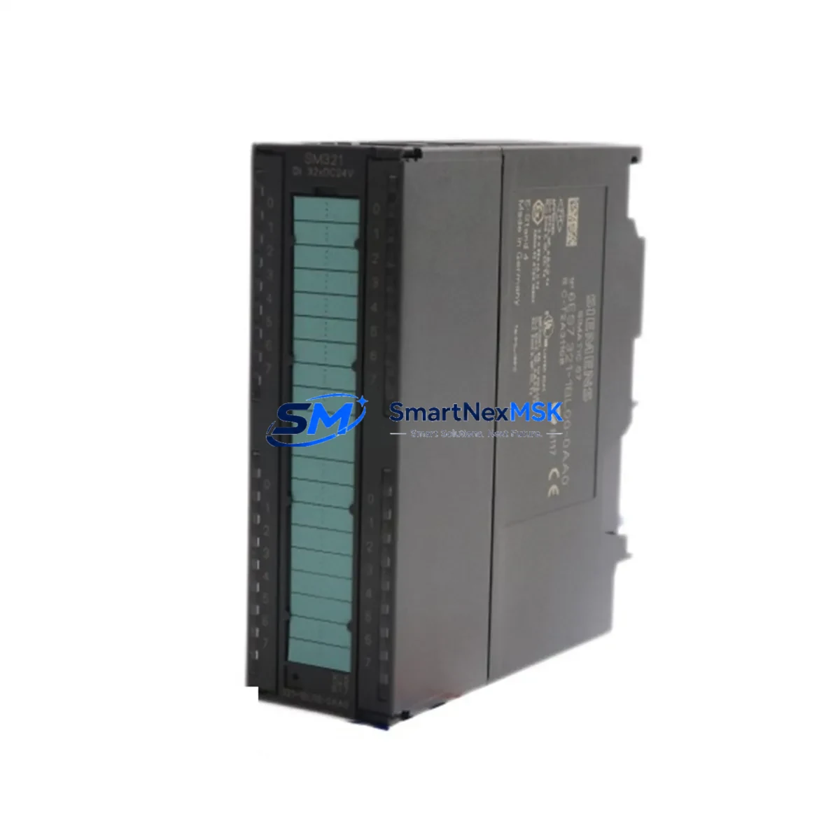
In industrial automation environments where uptime is non-negotiable, having a verified, maintenance-ready spare for the Siemens 6ES7321-1BL00-0AA0 32-channel digital input module is a cornerstone of any responsible S7-300 maintenance strategy. This SM 321 module — part of the SIMATIC S7-300 signal module family — handles 32 discrete 24 VDC input channels, making it one of the most widely deployed I/O modules across manufacturing, process control, and utility automation systems worldwide. When this module fails or degrades, the impact on production is immediate: field signals go dark, the CPU loses visibility into process states, and operators face unplanned shutdowns that can cost thousands per hour.
Sourced as an original Siemens component and fully tested prior to shipment, this spare is engineered to slot directly into existing S7-300 racks without configuration changes, firmware updates, or hardware modifications. Whether you are managing a planned annual overhaul, responding to an emergency fault, or building out a proactive spare parts inventory for a critical control cabinet, the 6ES7321-1BL00-0AA0 is a high-priority line item that should never be absent from your stockroom.
Spare Maintenance Table
| Parameter | Specification |
|---|---|
| Part Number | 6ES7321-1BL00-0AA0 |
| Series | SIMATIC S7-300 |
| Module Type | SM 321 Digital Input Module |
| Number of Inputs | 32 channels |
| Input Voltage | 24 VDC |
| Input Current (per channel) | Approx. 7 mA at 24 VDC |
| Isolation | Optocoupler isolation, 500 VAC group isolation |
| Backplane Bus Interface | S7-300 P-bus / K-bus compatible |
| Installation | DIN rail, S7-300 rack slot (any signal module slot) |
| Operating Temperature | 0 °C to +60 °C |
| Storage Temperature | -40 °C to +70 °C |
| Dimensions (W×H×D) | 40 mm × 125 mm × 120 mm |
| Weight | Approx. 240 g |
| Origin | Germany |
| Compatibility | All S7-300 CPUs (CPU 312 to CPU 319), IM 360/361/365 expansion racks |
| Condition | Original, new or refurbished-to-spec, tested before shipment |
| Warranty | 12 Months |
Maintenance Planning for Continuous Operation
Replacing the 6ES7321-1BL00-0AA0 in a live S7-300 system is rarely an isolated task. Experienced maintenance engineers know that a digital input module failure is often a symptom of broader electrical stress in the control cabinet, and a thorough replacement procedure should encompass a systematic inspection of all interconnected components.
Begin with the PS 307 power supply module (e.g., 6ES7307-1EA01-0AA0) — verify output voltage stability at 24 VDC under load, as voltage sag or ripple is a leading cause of premature I/O module failure. Next, inspect the front connector (6ES7392-1BM01-0AA0, 40-pin) for pin corrosion, loose terminations, and insulation damage; a degraded connector can cause intermittent channel faults that mimic module failure. Check the S7-300 rack (UR2 or UR1) backplane bus contacts for oxidation, particularly in high-humidity or chemically aggressive environments.
On the field wiring side, review the terminal block assemblies and cable shields connected to the 32 input channels. Unshielded or improperly grounded signal cables introduce noise that can cause false input states, especially in proximity to variable frequency drives or high-current switching loads. If the system uses signal isolators or intrinsic safety barriers between field sensors and the S7-300 inputs, verify their output voltage levels and response times remain within the module’s input threshold specifications.
For systems with expansion racks, inspect the IM 360/IM 361 interface modules and the connecting cable for continuity and secure seating. A marginal interface module connection can cause entire rack segments to drop offline, making it appear as though individual I/O modules have failed. Similarly, if the cabinet houses a CP 343-1 Ethernet communication module or a CP 342-5 PROFIBUS DP module, confirm their diagnostic LEDs show normal status — communication faults can cascade into I/O read errors at the CPU level.
During planned maintenance windows, it is also advisable to inspect the CPU 315-2 PN/DP or whichever CPU governs this rack, reviewing its diagnostic buffer for any logged I/O access errors, watchdog events, or STOP mode entries that preceded the module fault. Cross-referencing these logs with the replacement timeline helps validate that the root cause has been addressed. Finally, if the system includes an OP 277 or TP 177 HMI panel, confirm that all process values linked to the replaced input channels are displaying correctly after the module swap and CPU restart.
Site Replacement Workflow
Step 1 — Pre-replacement verification: Confirm the replacement module’s order number matches 6ES7321-1BL00-0AA0 exactly. Do not substitute with 6ES7321-1BH02-0AA0 (16-channel variant) or other SM 321 sub-types without verifying channel count and wiring compatibility with your existing front connector and I/O address assignments in the STEP 7 or TIA Portal hardware configuration.
Step 2 — Safe isolation: Place the CPU in STOP mode via the mode selector switch or STEP 7/TIA Portal. De-energize the 24 VDC field supply feeding the input channels. Do not rely solely on software STOP — physically isolate field power to prevent live-wire contact during connector removal.
Step 3 — Module extraction: Release the front connector locking mechanism and carefully unplug the 40-pin front connector. Note the slot position for reinstallation. Slide the module out of the rack by releasing the top and bottom mounting clips. The S7-300 hot-swap capability is CPU-dependent; verify your CPU supports online module replacement before attempting live swaps.
Step 4 — Module installation: Insert the replacement 6ES7321-1BL00-0AA0 into the same rack slot. The module is mechanically keyed to prevent incorrect insertion. Reconnect the front connector — the connector retains its wiring, so no re-termination is required if the connector is undamaged. Re-energize field power.
Step 5 — System restart and validation: Switch the CPU back to RUN mode. Monitor the module’s SF (System Fault) and EXTF LEDs — both should be off under normal operation. In STEP 7 or TIA Portal, perform an online diagnostic to confirm all 32 channels are reading correctly. Validate process values against known field sensor states before releasing the system to production.
This workflow supports legacy S7-300 systems operating on older STEP 7 V5.x projects as well as modernized installations managed under TIA Portal V16 and above, ensuring backward compatibility and minimal reengineering effort during emergency replacements.
Spare Parts Support FAQ
Q1: Is the 6ES7321-1BL00-0AA0 still available as a new original part, or only as refurbished stock?
Both new original and professionally refurbished-to-specification units are available. All units undergo functional testing across all 32 input channels prior to shipment. Refurbished units are restored to OEM electrical and mechanical specifications and carry the same 12-month warranty as new stock. Availability is confirmed at time of order inquiry.
Q2: How do I verify compatibility with my existing S7-300 hardware configuration before ordering?
The 6ES7321-1BL00-0AA0 is compatible with all standard S7-300 CPUs and UR1/UR2 racks. Compatibility is determined by the hardware configuration in your STEP 7 or TIA Portal project — open the hardware catalog, locate the SM 321 family, and confirm the order number matches. No firmware version dependency exists for this module type. If you are replacing a module in an expansion rack, verify the IM 360/361 interface module firmware supports your CPU version.
Q3: What is included in the pre-shipment testing process?
Each unit is tested for correct backplane bus communication, channel-by-channel input response verification at 24 VDC, isolation integrity between channel groups, and LED indicator functionality. Units that fail any test parameter are rejected from the shipment pool. A test report is available upon request for critical infrastructure procurement.
Q4: What does the 12-month warranty cover, and what is the replacement process if a fault occurs?
The 12-month warranty covers all manufacturing defects, functional failures under normal operating conditions, and early-life failures attributable to the module itself. It does not cover damage from incorrect installation, overvoltage events, or physical mishandling. In the event of a warranty claim, contact sales@smartnexmsk.com with your order number and fault description. Replacement units are dispatched upon fault confirmation, with priority processing for production-critical applications.
© 2026 SMARTNEXMSK. All rights reserved.
Original Source: https://smartnexmsk.com
Contact: sales@smartnexmsk.com | +86 18259474341


