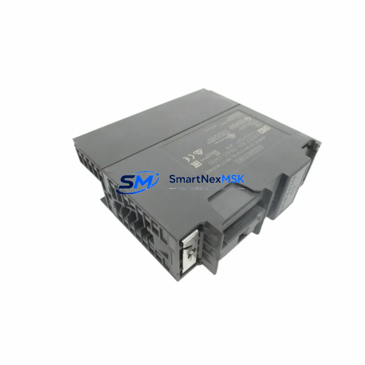
Siemens 6ES7321-7BH01-0AB0 Retrofit-Ready DI Module for S7-300 Control Systems
The Siemens 6ES7321-7BH01-0AB0 is a 16-channel digital input module (SM321, DI16 × DC 24V) designed for the SIMATIC S7-300 programmable logic controller platform. As legacy S7-300 installations continue to operate across manufacturing, process control, and infrastructure sectors, this module has become a critical retrofit and replacement component for engineers managing aging control cabinets, discontinued spare parts, and system modernization projects. Whether you are replacing a failed module on an active production line, upgrading a control panel to extend its operational life, or migrating from an older S5 or early S7-300 configuration, the 6ES7321-7BH01-0AB0 provides a verified, drop-in compatible solution with minimal downtime impact.
Upgrade Compatibility Table
| Parameter | Details |
|---|---|
| Module Type | SM321 Digital Input Module |
| Channels | 16 × DC 24V Digital Inputs |
| Input Voltage | DC 24V (rated), compatible with standard field sensor wiring |
| Backplane Interface | S7-300 standard bus connector (P-bus), compatible with UR1, UR2, UR2-H, and CR2 racks |
| Installation | DIN rail mounting via S7-300 rack; no additional hardware required |
| Communication Compatibility | Fully compatible with PROFIBUS-DP and MPI networks via CPU backplane |
| Replacement Recommendation | Direct replacement for 6ES7321-1BH02-0AA0 and other SM321 DI16 variants |
| Commissioning Notes | Verify module address slot assignment in STEP 7 or TIA Portal; re-download hardware configuration if required |
| Warranty | 12-Month Warranty — covers manufacturing defects and functional failures under normal operating conditions |
Retrofit Planning for Existing Automation Systems
Successful integration of the 6ES7321-7BH01-0AB0 into an existing S7-300 control system requires careful pre-installation planning. Before removing the failed or obsolete module, engineers should document the current slot address, terminal wiring layout, and any module-specific parameters configured in the hardware catalog. The 40-pin front connector used on SM321 modules is removable, which significantly reduces rewiring time during hot-swap replacement scenarios — the connector can be transferred directly from the old module to the new one, preserving all field wiring.
Power budget verification is essential when adding or replacing modules in an existing rack. The S7-300 power supply module — commonly the PS307 5A or PS307 10A — must provide sufficient current for all installed I/O modules. When upgrading a rack that also includes analog input modules such as the SM331 AI8, output modules like the SM322 DO16, or specialty modules such as the SM338 position input module, the total current draw must be recalculated to avoid supply overload. If the existing power supply is operating near capacity, consider upgrading to a higher-rated PS307 unit before completing the retrofit.
For systems using PROFIBUS-DP for distributed I/O, confirm that the CPU — whether a CPU 315-2 DP, CPU 317-2 DP, or CPU 319-3 PN/DP — retains its DP master configuration and that the GSD file for any ET 200 remote I/O stations remains intact. If the control system includes ET 200S or ET 200M distributed I/O nodes connected via PROFIBUS, these must be verified online after the CPU restart to confirm all slaves are recognized. Communication modules such as the CP 342-5 PROFIBUS processor should also be checked for active connections following any rack power cycle.
In control cabinets where the S7-300 rack is mounted alongside an OP 277 or TP 277 HMI panel, the HMI project should be reviewed to confirm that any I/O tags mapped to the replaced module’s channel addresses remain valid. If the module type has changed — for example, from a 16-channel isolated input variant to the standard 6ES7321-7BH01-0AB0 — the HMI tag database may require a partial update to reflect any differences in diagnostic behavior or input signal representation. This is particularly relevant in systems where the HMI displays real-time field sensor status or alarm states derived from digital input channels.
For older installations migrating from SIMATIC S5 hardware, the retrofit path typically involves replacing S5-115U or S5-135U digital input cards with S7-300 SM321 modules, often in conjunction with a CPU replacement and a full program conversion using the STEP 5 to STEP 7 migration tool. In these scenarios, the 6ES7321-7BH01-0AB0 serves as the target I/O module in the new S7-300 rack, and the terminal wiring from the original S5 front connectors must be remapped to the S7-300 40-pin connector layout. A programming cable such as the PC Adapter USB A2 is required to connect a laptop to the MPI port of the new CPU for initial program download and hardware configuration.
Downtime Control During System Migration
Minimizing production downtime during a module replacement or system migration is a primary concern for maintenance engineers working on live automation systems. The 6ES7321-7BH01-0AB0’s removable front connector design is a key advantage: by pre-wiring the new module’s connector before the scheduled maintenance window, the physical swap can be completed in under five minutes. The CPU can be placed in STOP mode, the old module removed, the new module inserted into the same rack slot, and the pre-wired connector attached — all without disturbing any field wiring.
Before initiating the swap, back up the current STEP 7 or TIA Portal project, including the hardware configuration and all program blocks (OBs, FBs, FCs, and DBs). If the replacement module is identical in type and firmware revision, the CPU will typically recognize it automatically upon restart without requiring a new hardware download. However, if there are any differences in module parameters — such as input filter times or diagnostic interrupt settings — a hardware configuration download will be necessary. In this case, the CPU will briefly enter STOP mode during the download before returning to RUN, which should be coordinated with the process control team to avoid unintended actuator states.
For critical processes where even brief interruptions are unacceptable, consider using the S7-300’s STOP/RUN transition in conjunction with output module hold-last-value settings on associated SM322 DO16 or SM332 AO4 modules to maintain field device states during the CPU restart. Document all steps in a formal change management record, and conduct a post-commissioning functional test of all 16 input channels using a signal simulator or by cycling the connected field devices through their normal operating states.
Retrofit Support FAQ
Q1: Is the 6ES7321-7BH01-0AB0 a direct replacement for the 6ES7321-1BH02-0AA0?
Yes. Both are SM321 DI16 × DC 24V modules for the S7-300 platform and share the same rack slot footprint, bus connector, and 40-pin front connector interface. The 7BH01 variant includes isolated input groups, which may offer improved noise immunity in certain applications. No hardware configuration changes are required if the module type is set identically in STEP 7 or TIA Portal.
Q2: Do I need to re-download the PLC program after replacing this module?
In most cases, no. If the replacement module is configured identically to the original in the hardware catalog, the CPU will recognize it automatically after a power cycle. A hardware configuration download is only required if module parameters have changed or if the CPU reports a configuration mismatch fault (SF LED active). Always verify the CPU’s diagnostic buffer after restart to confirm clean operation.
Q3: How do I verify wiring compatibility before installation?
Compare the terminal assignment diagram of the 6ES7321-7BH01-0AB0 (available in the SM321 module manual, document number 6ES7321-7BH01-0AB0) with the existing wiring on the front connector. The 40-pin connector layout is standardized across most SM321 variants, but isolated input groups may have different common terminal assignments. Use a multimeter to verify signal continuity on each channel before powering up the system.
Q4: What does the 12-month warranty cover?
All units supplied by SMARTNEXMSK carry a 12-month warranty covering manufacturing defects and functional failures under normal operating conditions. If a module fails within the warranty period, we provide a replacement or full refund after fault verification. Units showing signs of physical damage, incorrect installation voltage, or unauthorized modification are excluded from warranty coverage. Contact sales@smartnexmsk.com for warranty claims and RMA processing.
© 2026 SMARTNEXMSK. All rights reserved.
Original Source: https://smartnexmsk.com
Contact: sales@smartnexmsk.com | +86 18259474341


