Siemens 6ES7322-1BH01-0AA0 Maintenance-Ready Spare for SM322 Automation
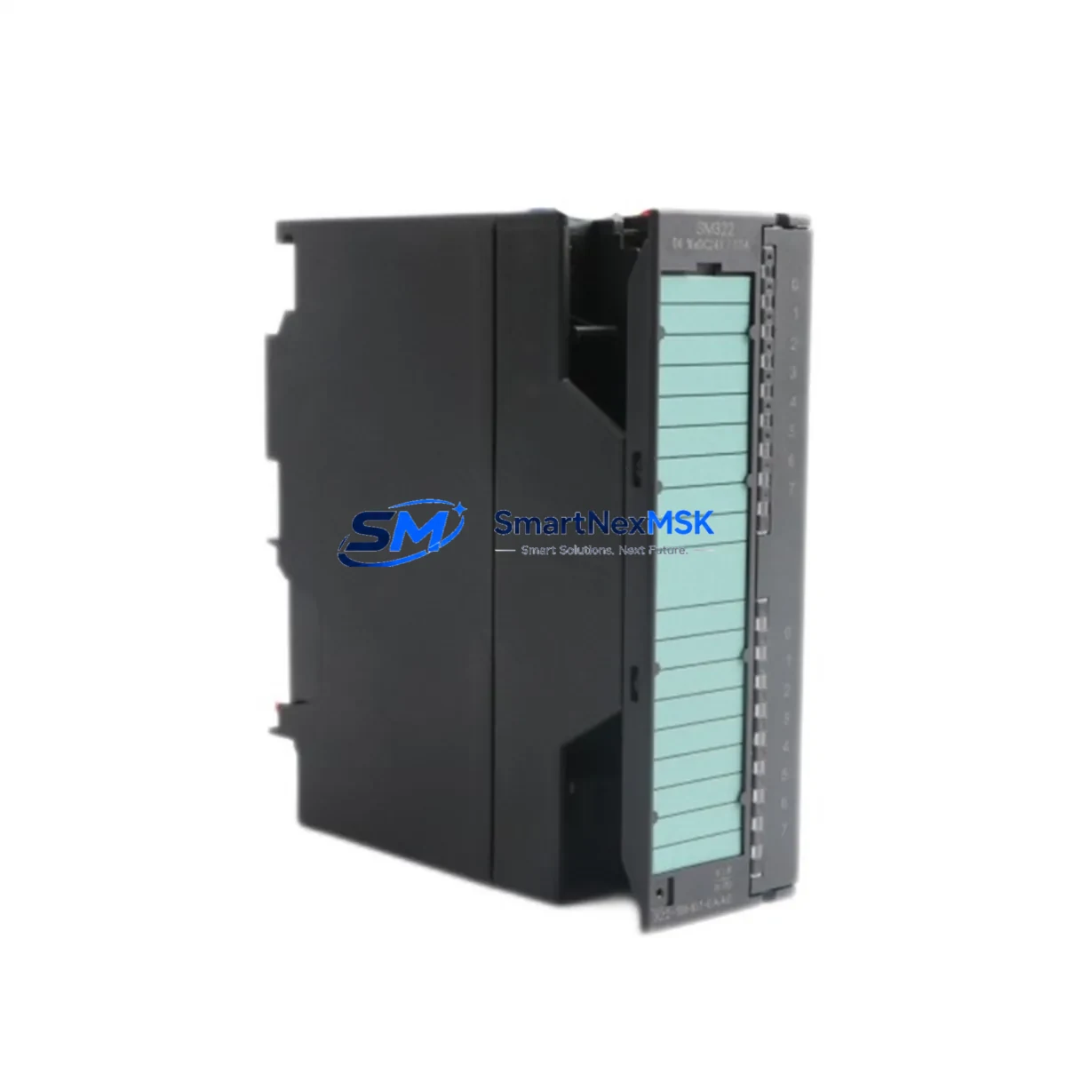
For maintenance engineers and procurement teams managing Siemens S7-300 control systems, unplanned downtime caused by a failed digital output module is one of the most disruptive events on the plant floor. The Siemens 6ES7322-1BH01-0AA0 is the SM322 series 16-channel digital output module rated at 24 VDC / 0.5 A per channel, designed for direct integration into S7-300 backplane racks. Sourcing a verified original spare — tested, documented, and ready to ship — is the fastest path from fault detection to full system restoration.
At SMARTNEXMSK, every unit of the 6ES7322-1BH01-0AA0 is inspected against Siemens factory specifications before dispatch. Whether you are executing a planned shutdown replacement, responding to an emergency fault alarm, or building a strategic spare parts buffer for a multi-line facility, this module ships with full traceability and a 12-month warranty covering manufacturing defects and functional failure under normal operating conditions.
Spare Maintenance Table
| Parameter | Specification |
|---|---|
| Part Number / SKU | 6ES7322-1BH01-0AA0 |
| Module Series | SM322 — Digital Output Module |
| Compatible PLC Platform | Siemens SIMATIC S7-300 |
| Number of Output Channels | 16 DO (Digital Outputs) |
| Output Voltage | 24 VDC |
| Output Current per Channel | 0.5 A |
| Total Current Load | 4 A (per module) |
| Isolation | Optocoupler-isolated outputs |
| Backplane Interface | S7-300 standard bus connector |
| Operating Temperature | 0 °C to +60 °C |
| Storage Temperature | -40 °C to +70 °C |
| Degree of Protection | IP20 |
| Country of Origin | Germany |
| Dimensions (W × H × D) | 40 × 125 × 120 mm (approx.) |
| Weight | ~200 g |
| Installation | DIN rail via S7-300 rack slot |
| Firmware / Configuration | Configured via STEP 7 / TIA Portal hardware catalog |
| Replacement Compatibility | Direct drop-in for 6ES7322-1BH00-0AA0 (predecessor) |
| Pre-shipment Testing | Functional output channel verification performed |
| Warranty | 12 Months — Manufacturing defect & functional failure |
Maintenance Planning for Continuous Operation
When a 6ES7322-1BH01-0AA0 digital output module triggers a fault — whether through a blown output channel, overtemperature shutdown, or bus communication error — the replacement process rarely ends with the module itself. Experienced maintenance engineers know that a failed DO module is often a symptom of broader stress in the control cabinet. A thorough site inspection should accompany every module swap.
Begin by verifying the 24 VDC load power supply feeding the output group. A degraded or undersized power supply unit — such as a Siemens SITOP PSU100S or equivalent — can cause repeated output module failures through voltage sag under load. Check the supply voltage at the module’s L+ terminal under full output load before installing the replacement.
Inspect the S7-300 backplane rack and bus connectors for oxidation, mechanical damage, or loose seating. A faulty bus connector between the CPU (e.g., a 6ES7315-2AG10-0AB0 or 6ES7314-1AG14-0AB0) and the SM322 module can cause intermittent communication faults that mimic module failure. Clean and reseat all connectors in the affected rack segment.
Review the SM321 digital input modules in the same rack. In many control architectures, input and output modules share the same 24 VDC supply rail. If the input module (e.g., 6ES7321-1BH02-0AA0) shows abnormal diagnostics, the root cause may be a shared supply issue rather than an isolated output fault.
Check the output wiring and field terminal blocks. Loose or corroded terminals on the front connector can cause high-resistance connections that stress individual output channels. Inspect the 40-pin front connector and associated terminal strips for signs of arcing or heat discoloration.
For systems using intermediate relay modules — such as Siemens ET 200 relay output modules or third-party relay terminal blocks — verify that the relay coil ratings match the 24 VDC / 0.5 A output specification of the SM322. Oversized relay coils can exceed the module’s per-channel current limit and cause premature output transistor failure.
If the S7-300 system includes a CP 343-1 Ethernet communication module or a DP master/slave interface (IM 360/361), confirm that the rack configuration in STEP 7 or TIA Portal still matches the physical hardware after the module replacement. A slot address mismatch will prevent the CPU from recognizing the new module and trigger a hardware configuration fault.
For facilities running signal isolators or loop-powered transmitters on the same 24 VDC bus, verify that the total current draw does not exceed the supply capacity after the module replacement. Adding a spare SM322 to an already-loaded supply rail without recalculating the current budget is a common cause of nuisance tripping.
Finally, update your spare parts inventory record to reflect the consumed unit and reorder to maintain your minimum stock level. For high-criticality lines, maintaining at least one additional 6ES7322-1BH01-0AA0 on the shelf — alongside a spare CPU module and at least one SM321 input module — is a recognized best practice for S7-300 system resilience.
Site Replacement Workflow
Step 1 — Fault Isolation: Identify the faulting module via the CPU diagnostic buffer in STEP 7 or TIA Portal. Note the rack and slot address of the 6ES7322-1BH01-0AA0 before powering down the affected rack segment.
Step 2 — Safe Isolation: De-energize the 24 VDC load supply to the output group. Do not rely solely on the CPU STOP mode — physically isolate the field load supply using the appropriate circuit breaker or fused disconnect. Verify zero voltage at the module’s L+ terminal with a calibrated multimeter.
Step 3 — Module Removal: Disconnect the 40-pin front connector. Release the module from the backplane by pressing the release lever and sliding the module out of the rack slot. Inspect the bus connector on the removed module for damage before discarding or returning it.
Step 4 — Replacement Installation: Insert the new 6ES7322-1BH01-0AA0 into the same rack slot. Ensure the bus connector is fully seated. Reconnect the 40-pin front connector, verifying that all field wiring terminals are correctly torqued (typically 0.5–0.6 Nm for standard S7-300 front connectors).
Step 5 — Configuration Verification: Power up the rack. In STEP 7 or TIA Portal, perform a hardware comparison to confirm the module is recognized at the correct slot address. Clear the CPU diagnostic buffer and switch the CPU to RUN mode. Verify all 16 output channels by executing a forced output test on non-critical channels before returning the system to automatic operation.
Step 6 — Documentation: Record the replacement in the maintenance log, including the date, replaced module serial number, technician name, and post-replacement test results. Update the spare parts inventory and initiate a reorder if stock falls below the minimum threshold.
This workflow minimizes mean time to repair (MTTR) and ensures the replacement is performed safely, with full system verification before returning to production. The 6ES7322-1BH01-0AA0 is a direct drop-in replacement for the earlier 6ES7322-1BH00-0AA0 variant, requiring no hardware configuration changes in most S7-300 installations.
Spare Parts Support FAQ
Q1: Is the 6ES7322-1BH01-0AA0 compatible with all S7-300 CPU variants?
Yes. The SM322 module communicates via the standard S7-300 backplane bus and is compatible with all S7-300 CPUs, including the 312, 313, 314, 315, 316, and 317 series. No firmware update is required on the CPU side. The module is configured automatically from the STEP 7 or TIA Portal hardware catalog upon CPU startup.
Q2: What pre-shipment testing is performed on each unit?
Each 6ES7322-1BH01-0AA0 dispatched from SMARTNEXMSK undergoes functional output channel verification: all 16 DO channels are activated and measured under a resistive load to confirm correct switching behavior and output voltage levels. Units that fail any channel test are quarantined and not shipped. A test report is available upon request for critical procurement requirements.
Q3: Can this module replace the older 6ES7322-1BH00-0AA0 without reconfiguring the PLC program?
In the vast majority of S7-300 installations, yes. The -1BH01- revision is the direct successor to the -1BH00- variant and maintains full hardware and software compatibility. The module occupies the same rack slot, uses the same front connector wiring, and is recognized by the same hardware catalog entry in STEP 7. Always verify the hardware configuration in your specific project before installation, particularly in systems with customized diagnostic routines.
Q4: What does the 12-month warranty cover, and how is a warranty claim processed?
The 12-month warranty covers manufacturing defects and functional failure under normal operating conditions (correct supply voltage, within rated current load, within specified temperature range). It does not cover damage caused by incorrect wiring, overvoltage events, or physical mishandling. To initiate a warranty claim, contact SMARTNEXMSK at sales@smartnexmsk.com with the order number, module serial number, and a description of the fault. Replacement units are dispatched after fault verification, typically within 3–5 business days.
© 2026 SMARTNEXMSK. All rights reserved.
Original Source: https://smartnexmsk.com
Contact: sales@smartnexmsk.com | +86 18259474341


