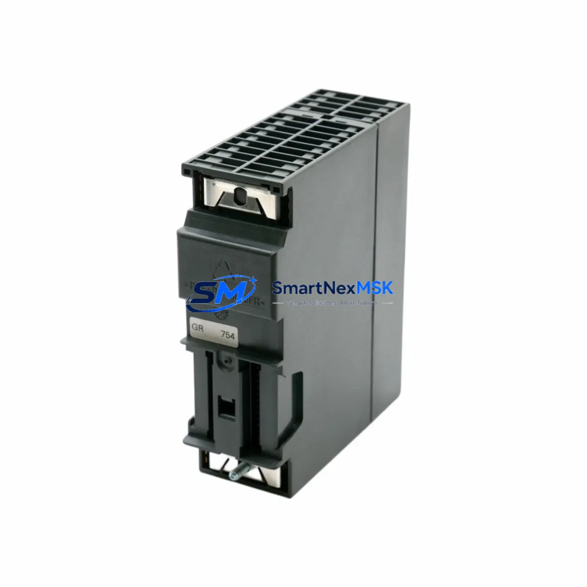
Siemens 6ES7322-1BP00-0AA0 Maintenance-Ready Spare for S7-300 Automation
The Siemens 6ES7322-1BP00-0AA0 is a 32-channel digital output module belonging to the SM 322 series within the SIMATIC S7-300 programmable logic controller platform. Designed for demanding industrial environments, this module delivers 24 VDC transistor outputs at 0.5 A per channel, making it a critical component in discrete control applications across manufacturing, process automation, packaging lines, and material handling systems. For maintenance engineers and procurement teams managing aging S7-300 installations, securing a verified spare of the 6ES7322-1BP00-0AA0 is a proactive step toward eliminating unplanned downtime and protecting long-term production continuity.
When this module fails or reaches end-of-service life, the impact on a production line can be immediate. Output channels go dark, actuators lose command signals, and the entire control loop dependent on that rack slot becomes inoperative. Having a pre-tested, shelf-ready 6ES7322-1BP00-0AA0 in your spare parts inventory means the difference between a 15-minute swap and a multi-day procurement emergency. Every unit shipped from our warehouse undergoes functional verification prior to dispatch, and is covered by a 12-month warranty against manufacturing and operational defects.
Spare Maintenance Table
| Parameter | Specification |
|---|---|
| SKU / Order Number | 6ES7322-1BP00-0AA0 |
| Module Type | SM 322 Digital Output Module |
| Output Channels | 32 × Transistor (24 VDC, 0.5 A per channel) |
| Output Voltage | 24 VDC (sourcing) |
| Load Current per Channel | 0.5 A max |
| Total Module Current | Max 4 A (aggregate) |
| Backplane Interface | S7-300 standard bus connector |
| Compatible Racks | UR1, UR2, ER1, ER2 (S7-300 series) |
| Compatible CPUs | CPU 313, 314, 315, 315-2 DP, 316, 317, 318 and variants |
| Wiring Method | 40-pin front connector (6ES7392-1AM00-0AA0 type) |
| Protection Class | IP20 |
| Operating Temperature | 0 °C to +60 °C |
| Weight | Approx. 300 g |
| Country of Origin | Germany |
| Warranty | 12 Months from date of shipment |
| Pre-shipment Test | Functional output verification on all 32 channels |
Maintenance Planning for Continuous Operation
Effective maintenance planning for an S7-300 control cabinet goes well beyond stocking a single output module. When a 6ES7322-1BP00-0AA0 is flagged for replacement during a scheduled inspection or emergency callout, the maintenance engineer should simultaneously audit the surrounding components to prevent secondary failures from extending the downtime window.
Start with the power supply. The PS 307 power supply module — available in 2 A, 5 A, and 10 A variants — feeds the entire S7-300 rack. A degraded PS 307 can cause intermittent output faults that mimic a failed SM 322 module, so verifying output voltage stability under load is a mandatory first step before condemning the 6ES7322-1BP00-0AA0. Similarly, inspect the backplane bus connector on the rack itself; a cracked or oxidized bus connector on the UR2 rack can cause communication errors that appear as module faults in the CPU diagnostic buffer.
The front connector wiring deserves careful attention. The 40-pin front connector (typically a 6ES7392-1AM00-0AA0) carries all field wiring to the output channels. During replacement, inspect each terminal for loose crimps, insulation damage, and correct torque. Mislabeled or reversed wiring is a common source of commissioning errors after a module swap. If the installation uses grouped commons, verify that the load group fusing — typically implemented with miniature circuit breakers or fuse terminal blocks in the field wiring panel — is intact and correctly rated for the 0.5 A per channel specification.
For sites running PROFIBUS DP networks, the CP 342-5 communications processor or the integrated DP interface on CPUs such as the CPU 315-2 DP should be checked for consistent bus timing and address conflicts, particularly if the rack was powered down abruptly during a fault condition. A corrupted GSD file or incorrect DP slave address can prevent the replacement module from being recognized by the master CPU after reinsertion.
Maintenance teams should also inspect the SM 321 digital input modules installed in adjacent slots. In many S7-300 cabinets, input and output modules share the same rack and power bus. A shorted field device connected to an SM 321 input channel can generate transient voltage spikes that stress output transistors on the 6ES7322-1BP00-0AA0, accelerating wear. Checking input channel diagnostics and field device insulation resistance before restoring power after a module replacement is a best practice that prevents repeat failures.
If the control system includes an HMI panel — such as a TP 177B or MP 277 connected via MPI — verify that the HMI project’s I/O tag addresses still map correctly to the replacement module’s slot position. Slot-based addressing in S7-300 means that if the module is reinstalled in a different slot than the original, all associated DB and tag references in the STEP 7 project must be updated accordingly. Keep a printed or PDF copy of the hardware configuration (HW Config) on file in the control cabinet for rapid reference during emergency maintenance.
Finally, for sites with analog output requirements in the same cabinet, the SM 332 analog output module and its associated shielded signal cables should be inspected for ground loops and cable integrity. Signal isolation barriers installed between the PLC output and field instrumentation can degrade over time and should be tested as part of any comprehensive cabinet inspection that involves replacing a digital output module.
Site Replacement Workflow
Replacing the 6ES7322-1BP00-0AA0 on a live S7-300 system requires a structured approach to minimize downtime and avoid configuration errors. Follow this workflow for a safe and efficient swap:
Step 1 — Pre-replacement preparation: Download and save the current STEP 7 hardware configuration and program blocks to an offline backup. Note the exact slot number of the failed module in the rack. Print or photograph the front connector wiring before disconnecting any terminals.
Step 2 — Safe isolation: Switch the CPU to STOP mode via the mode selector switch or through SIMATIC Manager. De-energize the load power supply feeding the output group. Do not remove the module while the rack is powered unless the system is specifically designed for hot-swap operation — standard S7-300 racks are not hot-swap capable.
Step 3 — Module removal: Unlock and remove the front connector by pressing the release lever. Slide the module out of the rack slot. Inspect the backplane bus connector pins for damage before inserting the replacement unit.
Step 4 — Replacement installation: Insert the 6ES7322-1BP00-0AA0 replacement into the same slot. Reconnect the front connector, ensuring all terminals are seated and torqued to specification (typically 0.5–0.6 Nm for standard S7-300 front connectors). Restore load power.
Step 5 — System restart and verification: Switch the CPU back to RUN mode. Monitor the diagnostic buffer in SIMATIC Manager for any module fault entries. Verify all 32 output channels by forcing test outputs through the variable table (VAT) and confirming field device response. Document the replacement date, module serial number, and test results in the maintenance log.
This structured workflow typically allows a trained maintenance engineer to complete a 6ES7322-1BP00-0AA0 replacement in under 30 minutes, keeping unplanned downtime to a minimum and restoring full production capacity quickly.
Spare Parts Support FAQ
Q1: Is the 6ES7322-1BP00-0AA0 still in production, and how long can I expect supply availability?
The 6ES7322-1BP00-0AA0 is part of the SIMATIC S7-300 product family, which Siemens has transitioned to a limited lifecycle phase. While new production quantities may be constrained, we maintain dedicated inventory of this module to support ongoing maintenance requirements. We recommend procurement teams secure a buffer stock of 1–2 units per active rack to protect against supply disruptions. All units are sourced from verified channels and carry a 12-month warranty.
Q2: How do I confirm compatibility before ordering?
The 6ES7322-1BP00-0AA0 is compatible with all standard S7-300 racks (UR1, UR2, ER1, ER2) and works with the full range of S7-300 CPUs that support SM 322 digital output modules. Compatibility is determined by the hardware configuration in your STEP 7 project — confirm that the module order number matches the entry in HW Config for the target slot. If you are replacing a module of a different channel count or output type, a hardware reconfiguration and program update will be required.
Q3: What pre-shipment testing is performed on each unit?
Every 6ES7322-1BP00-0AA0 unit undergoes functional verification prior to dispatch. Testing includes power-on self-test, channel-by-channel output activation verification across all 32 channels, and bus communication check. Units that fail any test criterion are quarantined and not shipped. A test report is available upon request. All shipped units are covered by a 12-month warranty from the date of shipment.
Q4: Can I use this module as a direct drop-in replacement without reprogramming?
Yes, provided the replacement module is installed in the same rack slot as the original and the order number matches exactly (6ES7322-1BP00-0AA0). The S7-300 CPU will recognize the module automatically upon restart without requiring a hardware reconfiguration download. If the slot position changes, or if you are substituting a module with a different order number, a new hardware configuration download from SIMATIC Manager will be necessary. Always verify output channel behavior through a forced I/O test before returning the system to automatic operation.
© 2026 SMARTNEXMSK. All rights reserved.
Original Source: https://smartnexmsk.com
Contact: sales@smartnexmsk.com | +86 18259474341


