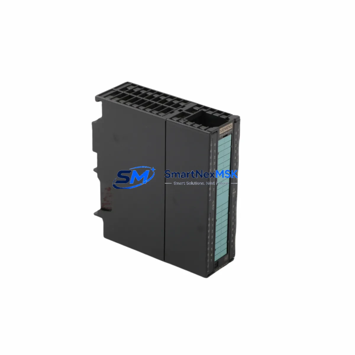
Siemens 6ES7323-1BL00-0AA0 Spare for S7-300 Automation: Spare Parts Replacement & Industrial Downtime Risk Control
The Siemens 6ES7323-1BL00-0AA0 is a 32-channel digital combination input/output module designed for the SIMATIC S7-300 programmable logic controller platform. With 16 digital inputs (24 V DC) and 16 digital outputs (24 V DC / 0.5 A), this SM 323 series module serves as a critical interface between field devices and the S7-300 CPU in discrete manufacturing, process control, and utility automation environments. When this module fails or reaches end-of-life, the entire control cabinet section it governs may go offline, triggering unplanned downtime that can cost thousands per hour in production loss. Maintaining a verified spare on the shelf is the most effective insurance against this risk.
At SMARTNEXMSK, every 6ES7323-1BL00-0AA0 unit is sourced from authorized supply chains, inspected against original Siemens specifications, and dispatched with a 12-month warranty. Each module undergoes functional verification prior to shipment, ensuring that the replacement you receive is ready to install without additional bench testing on site.
Spare Maintenance Table
| Parameter | Specification |
|---|---|
| Part Number / SKU | 6ES7323-1BL00-0AA0 |
| Module Family | SM 323 — Digital Combination I/O |
| Compatible Platform | SIMATIC S7-300 (all CPU variants) |
| Digital Inputs | 16 × 24 V DC (IEC Type 1 / Type 2) |
| Digital Outputs | 16 × 24 V DC, 0.5 A, transistor sourcing |
| Supply Voltage (L+) | 24 V DC (20.4 – 28.8 V) |
| Current Consumption (backplane bus) | Max. 100 mA (5 V DC) |
| Current Consumption (L+) | Max. 120 mA (no load) |
| Isolation | Optocoupler isolation, 500 V AC group isolation |
| Backplane Interface | S7-300 standard rail / bus connector |
| Mounting | DIN rail, S7-300 profile rail |
| Operating Temperature | 0 °C to +60 °C (horizontal), 0 °C to +40 °C (vertical) |
| Storage Temperature | –40 °C to +70 °C |
| Degree of Protection | IP 20 |
| Country of Origin | Germany |
| HS Code | 8537.10 |
| Compatibility Verified | Drop-in replacement for all S7-300 rack positions |
| Maintenance Recommendation | Inspect bus connector pins, 24 V supply fuse, and field wiring terminals at each planned maintenance interval |
| Warranty | 12 Months — covers manufacturing defects and functional failure under normal operating conditions |
Maintenance Planning for Continuous Operation
When a 6ES7323-1BL00-0AA0 module is flagged for replacement during a planned shutdown or emergency callout, experienced maintenance engineers know that the module itself is rarely the only component that needs attention. A thorough inspection of the surrounding control cabinet is essential to prevent repeat failures and ensure the replacement module operates reliably from day one.
Begin with the 24 V DC power supply feeding the module’s L+ terminal. A degraded SITOP PSU100S or equivalent 24 V regulated supply can cause intermittent output faults that mimic module failure. Verify output voltage under load and check for ripple exceeding 5% before declaring the module at fault. Alongside the power supply, inspect the S7-300 bus connector (6ES7390-0AA00-0AA0) seated between this module and its neighbor — cracked or oxidized bus connectors are a leading cause of sporadic I/O errors in aging S7-300 racks.
Check the front connector (6ES7392-1BM01-0AA0 or 6ES7392-1BJ00-0AA0) for terminal corrosion, loose screw connections, and insulation damage on field cables. In high-vibration environments, terminal screws can back off over time, causing intermittent signal loss that is difficult to diagnose remotely. While the front connector is removed, this is also the right moment to inspect the 24 V DC fuse or miniature circuit breaker protecting the output group — a nuisance trip here will disable all 16 outputs simultaneously.
If the S7-300 rack hosts a CP 343-1 Ethernet communication module or a CP 342-5 PROFIBUS DP module, verify that the network connection is stable and that the CPU is not reporting any communication faults that could be masking an underlying I/O issue. In distributed I/O architectures, an ET 200M remote I/O station with its own IM 153-2 interface module may be sharing the same PROFIBUS segment — confirm that the bus termination resistors are correctly set at both ends of the segment.
For facilities running mixed analog and digital I/O in the same cabinet, check adjacent SM 331 analog input modules (e.g., 6ES7331-7KF02-0AB0) for ground loop issues that can introduce noise into the digital input channels of the 6ES7323-1BL00-0AA0. A signal isolator or galvanic separator on shared 0 V reference lines is a low-cost preventive measure that significantly extends module service life. Finally, review the S7-300 CPU 315-2 DP or CPU 314C-2 DP diagnostic buffer for any hardware fault entries logged prior to the module failure — these entries often reveal whether the root cause was an external field fault, a wiring short, or a genuine module defect.
Stocking one spare 6ES7323-1BL00-0AA0 per production line, alongside a spare bus connector and front connector set, is the minimum recommended inventory posture for facilities where S7-300 systems are still in active service. For sites with more than five S7-300 racks, a two-unit spare holding is advisable to cover simultaneous failures during peak production periods.
Site Replacement Workflow
Step 1 — Isolate and de-energize. Switch the 24 V DC supply to the affected module group to OFF. Confirm zero voltage at the L+ terminal with a calibrated multimeter before touching any wiring.
Step 2 — Record the slot address. Note the rack number and slot number of the 6ES7323-1BL00-0AA0 being removed. In STEP 7 or TIA Portal, the hardware configuration assigns a fixed I/O address range to this slot — the replacement module must occupy the identical slot to avoid address conflicts.
Step 3 — Remove the front connector. Unscrew the front connector retaining screw and pull the connector forward. The front connector retains all field wiring, so no individual wires need to be disconnected. Label the connector if there is any risk of confusion with adjacent modules.
Step 4 — Release the bus connector. Open the module’s top and bottom mounting clips and slide the module forward off the profile rail. The bus connector will remain attached to the neighboring module — inspect it visually before proceeding.
Step 5 — Install the replacement module. Slide the new 6ES7323-1BL00-0AA0 onto the rail, engage the bus connector, and lock the mounting clips. Re-attach the front connector. The module does not require any DIP switch or jumper configuration — all parameters are downloaded from the CPU.
Step 6 — Re-energize and verify. Restore 24 V DC supply. The CPU should recognize the module automatically within one scan cycle. Check the module’s SF (System Fault) and I/O status LEDs. In TIA Portal or STEP 7, perform an online diagnostic to confirm all 32 channels are reporting correctly. Run a forced I/O test on a representative sample of input and output channels before returning the system to automatic mode.
This workflow typically achieves a complete module swap in under 20 minutes for a trained technician, minimizing production downtime to a single shift interruption rather than an extended outage.
Spare Parts Support FAQ
Q1: Is the 6ES7323-1BL00-0AA0 still available as a new original part, or only as a refurbished unit?
Siemens has transitioned the S7-300 platform to limited availability status, but original new-stock 6ES7323-1BL00-0AA0 modules remain available through authorized distributors and specialist suppliers such as SMARTNEXMSK. All units we supply are original Siemens manufacture — we do not supply refurbished, repaired, or third-party clone modules. Each unit is accompanied by original packaging and traceable batch documentation where available.
Q2: How do I verify compatibility before installation?
The 6ES7323-1BL00-0AA0 is a direct drop-in replacement for any SM 323 slot in an S7-300 rack. No hardware configuration change is required in STEP 7 or TIA Portal provided the replacement module occupies the same rack slot as the original. If you are replacing an older revision of the same part number, the firmware revision is backward-compatible. We recommend downloading the current hardware configuration to the CPU after replacement to clear any stored fault codes.
Q3: What does the 12-month warranty cover, and what is the return process?
The 12-month warranty covers all manufacturing defects and functional failures under normal operating conditions (correct supply voltage, within rated temperature range, no physical damage). If a module fails within the warranty period, contact sales@smartnexmsk.com with your order number and a brief fault description. We will arrange a replacement dispatch — in most cases within 48 hours — and provide a return shipping label for the defective unit. Warranty claims are processed without requiring the customer to send the defective unit back first for critical production situations.
Q4: Can SMARTNEXMSK support long-term supply for facilities running legacy S7-300 systems?
Yes. We maintain standing stock of high-demand S7-300 spare modules and can establish a framework supply agreement for facilities with ongoing maintenance requirements. Long-term supply agreements include reserved stock allocation, priority dispatch, and fixed pricing for the agreement period — protecting your maintenance budget from spot-market price volatility as S7-300 components become increasingly scarce. Contact our technical sales team to discuss your site’s specific spare parts list and annual consumption forecast.
© 2026 SMARTNEXMSK. All rights reserved.
Original Source: https://smartnexmsk.com
Contact: sales@smartnexmsk.com | +86 18259474341


