Siemens 6ES7332-5HF00-0AB0 Maintenance-Ready Spare for S7-300 Automation
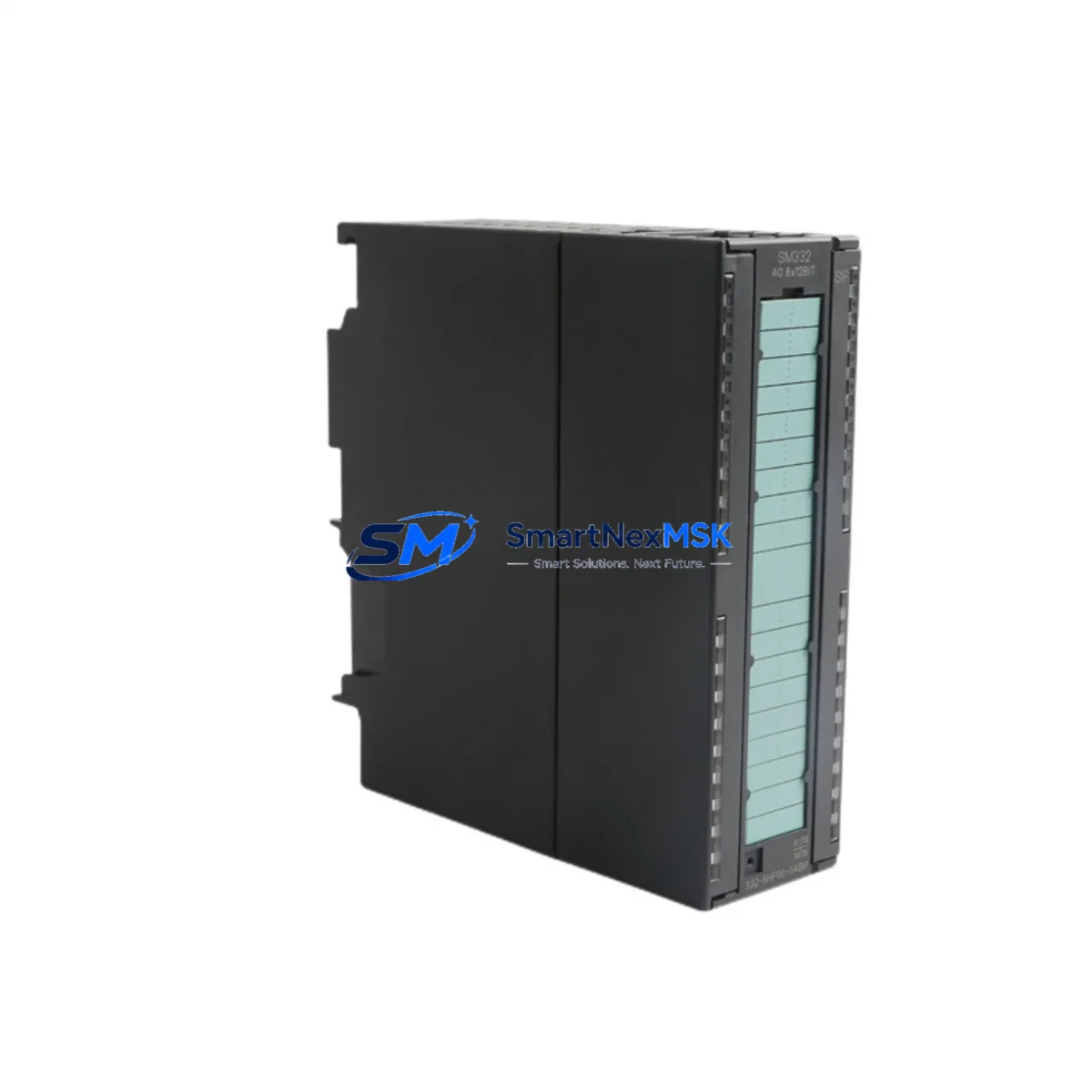
The Siemens 6ES7332-5HF00-0AB0 is an 8-channel analog output module designed for the SIMATIC S7-300 programmable logic controller platform. In industrial automation environments where continuous operation is non-negotiable, maintaining a verified spare of this module is a fundamental element of any proactive maintenance strategy. Unplanned downtime caused by a failed analog output channel can halt production lines, disrupt process control loops, and trigger cascading failures across connected field devices. Sourcing a tested, original-specification replacement in advance is the most effective way to minimize mean time to repair (MTTR) and protect operational continuity.
This module delivers 8 channels of analog output with configurable signal ranges including ±10 V, 0–20 mA, and 4–20 mA, making it suitable for driving proportional valves, variable-speed drives, positioners, and other field actuators in process and discrete manufacturing applications. It mounts directly onto the S7-300 backplane rail and communicates via the internal P-bus, requiring no additional interface hardware when replacing a like-for-like unit.
Every unit dispatched from our warehouse undergoes functional verification prior to shipment. Output channel accuracy, load compliance, and bus communication integrity are confirmed before packaging. A 12-month warranty is included with every order, covering manufacturing defects and functional failures under normal operating conditions.
Spare Maintenance Table
| Parameter | Specification |
|---|---|
| Part Number | 6ES7332-5HF00-0AB0 |
| Brand | Siemens |
| Series | SIMATIC S7-300 |
| Module Type | Analog Output Module (SM 332) |
| Number of Channels | 8 AO |
| Output Signal Ranges | ±10 V / 0–20 mA / 4–20 mA (configurable per channel) |
| Resolution | 11-bit + sign |
| Supply Voltage | DC 24 V (via backplane bus) |
| Load Impedance (Voltage) | ≥ 1 kΩ |
| Load Impedance (Current) | ≤ 600 Ω |
| Backplane Interface | S7-300 P-bus (direct rail mount) |
| Dimensions (W×H×D) | 40 × 125 × 120 mm |
| Weight | Approx. 280 g |
| Operating Temperature | 0 °C to +60 °C |
| Storage Temperature | −40 °C to +70 °C |
| Protection Rating | IP20 |
| Origin | Germany |
| Compatibility | SIMATIC S7-300 (all CPU variants with SM slot) |
| Replaces / Compatible With | 6ES7332-5HF00-0AB0 (direct replacement) |
| Condition | Original, New or Tested Surplus |
| Pre-shipment Test | Functional output channel and bus communication verified |
| Warranty | 12 Months |
Maintenance Planning for Continuous Operation
When a 6ES7332-5HF00-0AB0 analog output module is flagged during a control cabinet inspection or fails during operation, the replacement procedure should be treated as part of a broader system health review rather than an isolated swap. Maintenance engineers and procurement engineers working on SIMATIC S7-300 systems should consider the following associated components as part of the same inspection cycle.
The 24 VDC backplane supply feeding the SM 332 module is typically sourced from a dedicated power supply module such as the PS 307 series (e.g., 6ES7307-1BA01-0AA0 or 6ES7307-1EA01-0AA0). A degraded or undersized power supply is a common root cause of intermittent analog output errors and should be load-tested whenever an output module is replaced. Similarly, the CPU module — whether a 6ES7315, 6ES7317, or 6ES7318 variant — should be checked for firmware consistency and diagnostic buffer entries that may indicate prior communication faults with the SM 332 slot.
On the field wiring side, the front connector (6ES7392-1BM01-0AA0 or equivalent 40-pin front connector) carries all analog output signals to terminal blocks and field devices. Inspect the connector for oxidized pins, loose crimps, or thermal discoloration before reinstalling. If the system uses shielded twisted-pair cables to proportional valves or variable-speed drives, verify shield grounding continuity at both the cabinet and field ends.
For systems with mixed I/O requirements, the SM 321 digital input modules and SM 322 digital output modules sharing the same rack should be visually inspected for indicator LED status. A rack-level fault can sometimes be misdiagnosed as a single-module failure. The IM 360/361 interface modules used in multi-rack S7-300 configurations should also be checked if the failing module is located in an expansion rack.
In process control applications, signal isolators and loop-powered barriers installed between the S7-300 analog outputs and field transmitters or actuators are frequently overlooked during fault isolation. A failed signal isolator can present symptoms identical to an analog output module fault. Checking the isolator output with a calibrated loop calibrator before condemning the SM 332 module can prevent unnecessary module replacement.
For facilities running legacy S7-300 systems beyond their standard product lifecycle, maintaining a structured spare parts inventory that includes the 6ES7332-5HF00-0AB0, associated front connectors, a backup CPU module, and at least one power supply module significantly reduces the risk of extended downtime due to parts unavailability. Long-term supply of original Siemens S7-300 components remains available through authorized industrial distributors and specialist spare parts suppliers.
Site Replacement Workflow
Step 1 — Preparation: Before removing the existing module, record the current hardware configuration using STEP 7 or TIA Portal (if using a compatible CPU). Export the hardware configuration file and note the slot address assigned to the SM 332 module. Confirm the replacement unit carries the identical order number (6ES7332-5HF00-0AB0) to ensure direct compatibility without reconfiguration.
Step 2 — Safe Isolation: Switch the CPU to STOP mode via the mode selector switch or via the programming interface. De-energize the 24 VDC load power supply feeding the analog output channels. Do not rely solely on the CPU STOP state — verify zero voltage at the front connector terminals using a calibrated multimeter before disconnecting field wiring.
Step 3 — Module Removal: Disconnect the front connector by pressing the release lever and pulling the connector forward. Loosen the module retaining screw at the top of the module, then slide the module upward and off the DIN rail. Handle the module by its housing — avoid contact with the backplane bus connector pins.
Step 4 — Replacement Installation: Slide the new 6ES7332-5HF00-0AB0 onto the DIN rail in the same slot position. Secure the retaining screw. Reconnect the front connector, ensuring the coding key is correctly aligned. Restore 24 VDC load power and switch the CPU back to RUN mode.
Step 5 — Functional Verification: Monitor the module’s SF and DC5V LEDs for normal status. Use STEP 7 or TIA Portal to confirm the module is recognized in the hardware configuration and that no diagnostic alarms are active. Verify analog output values at the field device level using a process calibrator or by observing actuator response.
This workflow supports a target replacement time of under 30 minutes for a trained maintenance technician, minimizing production downtime and restoring system operation with full compatibility.
Spare Parts Support FAQ
Q1: Is the 6ES7332-5HF00-0AB0 still available as a new original part?
The SIMATIC S7-300 product line has reached end-of-sale status with Siemens, but original new and tested surplus units of the 6ES7332-5HF00-0AB0 remain available through specialist industrial spare parts suppliers. All units we supply are sourced from verified channels and undergo pre-shipment functional testing. Long-term availability is supported for existing installed base maintenance.
Q2: How do I confirm compatibility before ordering?
The 6ES7332-5HF00-0AB0 is compatible with all SIMATIC S7-300 CPUs that support signal module (SM) slots, including the CPU 313, 314, 315, 317, and 318 families. Compatibility is determined by the S7-300 backplane slot assignment in your hardware configuration, not by the CPU firmware version. If you are replacing an existing SM 332 module of the same order number, no hardware reconfiguration is required.
Q3: What does the 12-month warranty cover?
The 12-month warranty covers functional failures and manufacturing defects under normal industrial operating conditions. It includes free replacement or repair of the module if it fails to perform to its published specification within the warranty period. The warranty does not cover damage resulting from incorrect installation, overvoltage events, or operation outside the specified environmental limits.
Q4: What is your typical lead time and shipping process?
In-stock units are dispatched within 1–2 business days of order confirmation. Each unit is individually packaged with anti-static protection and accompanied by a test report. Express international shipping options are available for urgent maintenance requirements. Contact our sales team to confirm current stock availability and lead time for your specific quantity requirement.
© 2026 SMARTNEXMSK. All rights reserved.
Original Source: https://smartnexmsk.com
Contact: sales@smartnexmsk.com | +86 18259474341


