Siemens 6ES7392-1BJ00-0AA0 Retrofit-Ready Front Connector for S7-300 Control Systems
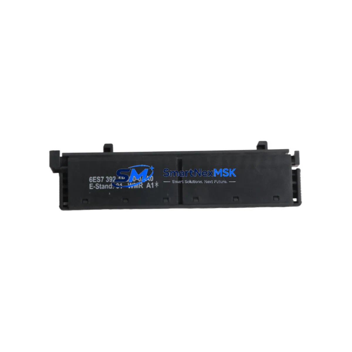
The Siemens 6ES7392-1BJ00-0AA0 is a 20-pin spring-clamp front connector designed for the SIMATIC S7-300 series of programmable logic controllers. As legacy S7-300 installations continue to operate across manufacturing, process control, and infrastructure sectors, this front connector remains a critical interface component — bridging field wiring to I/O modules, digital output modules, analog input modules, and signal modules throughout the control cabinet. Whether you are replacing a worn connector on an aging production line, upgrading a control panel after years of continuous operation, or restoring a system following an unplanned shutdown, the 6ES7392-1BJ00-0AA0 provides a direct, code-compatible, and mechanically interchangeable solution.
This connector is compatible with the full range of S7-300 signal modules that accept 20-pin front connectors, including SM 321 digital input modules, SM 322 digital output modules, SM 331 analog input modules, and SM 332 analog output modules. It supports spring-clamp termination for conductors up to 1.5 mm², enabling fast, tool-reduced field wiring during retrofit and commissioning. The connector slides onto the module face and locks mechanically, maintaining contact integrity even in high-vibration industrial environments.
When planning a retrofit or spare-parts replenishment for an S7-300 system, engineers typically audit the entire control rack. A standard S7-300 rack — such as the UR2 or UR1 mounting rail — may house a CPU 314, CPU 315-2 DP, or CPU 317-2 PN/DP alongside multiple signal modules, each requiring its own front connector. The 6ES7392-1BJ00-0AA0 is the correct connector for 20-pin modules; for 40-pin modules such as high-density I/O cards, the 6ES7392-1AM00-0AA0 is the appropriate counterpart. Stocking both variants ensures full coverage across a mixed-module rack.
Upgrade Compatibility Table
| Parameter | Details |
|---|---|
| SKU / Part Number | 6ES7392-1BJ00-0AA0 |
| Compatible Series | SIMATIC S7-300 |
| Pin Count | 20-pin |
| Termination Type | Spring-clamp (screwless) |
| Compatible Module Types | SM 321, SM 322, SM 331, SM 332 (20-pin variants) |
| Mounting Rail Compatibility | S7-300 UR1, UR2, UR2-H standard DIN rails |
| Installation Requirement | Snap-fit onto module front face; no tools required for wiring |
| Communication Compatibility | Passive field-wiring interface; compatible with PROFIBUS DP and PROFINET I/O module configurations |
| Replacement Recommendation | Direct drop-in replacement for all 6ES7392-1BJ00-0AA0 installations |
| Commissioning Notes | Verify terminal labeling against existing wiring diagram before re-termination; re-use existing cable markers |
| Warranty | 12-Month Warranty — covers manufacturing defects and contact failure under normal operating conditions |
Retrofit Planning for Existing Automation Systems
A successful S7-300 retrofit begins well before the first terminal is loosened. The 6ES7392-1BJ00-0AA0 front connector is typically replaced as part of a broader control cabinet refurbishment that may also involve swapping aging power supply modules such as the PS 307 5A or PS 307 10A, replacing deteriorated terminal blocks on the field-wiring side, and verifying the integrity of the backplane bus connector between adjacent modules. In multi-rack configurations, the IM 360 and IM 361 interface modules that link expansion racks to the central rack should also be inspected, as bus communication errors can masquerade as I/O faults when the root cause is a degraded connector or rack interface.
For systems communicating over PROFIBUS DP, the retrofit window is also an opportunity to audit the DP network topology. The CPU’s MPI/DP port, the CP 342-5 PROFIBUS communication processor, and all field device addresses should be documented before any module is removed. If the retrofit involves migrating from S7-300 to S7-1500, the new CPU 1515-2 PN or CPU 1516-3 PN/DP will require a different front connector form factor, but the field wiring termination philosophy remains similar — making the 6ES7392-1BJ00-0AA0 a useful reference point for wiring documentation continuity.
During the physical retrofit, engineers should photograph the existing wiring layout on each front connector before removal. Spring-clamp connectors like the 6ES7392-1BJ00-0AA0 allow individual conductors to be released with a standard screwdriver inserted into the release slot, enabling systematic re-termination without cutting cables. Each conductor should be re-inserted and verified for seating before the connector is re-engaged onto the module. After re-engagement, a continuity check across each terminal pair confirms correct wiring before the CPU is powered up and the user program is restarted.
Where the retrofit also involves replacing the programming cable or updating the STEP 7 project, the PC Adapter USB A2 or SIMATIC NET CP 5711 can be used to re-establish a programming connection to the CPU. If the HMI panel — such as a TP700 Comfort or KTP900 Basic — is connected via PROFINET or MPI, its communication parameters should be verified against the CPU’s updated network configuration to avoid HMI communication faults after the retrofit is complete.
Downtime Control During System Migration
Minimizing unplanned downtime during a front connector replacement or broader S7-300 retrofit requires a structured approach. The recommended sequence is: first, perform a full CPU memory backup using a SIMATIC Memory Card or via STEP 7 online save to the programming device. This preserves the current user program, data blocks, and hardware configuration, ensuring that if any issue arises during the retrofit, the system can be restored to its last known good state without re-programming from scratch.
Second, document all I/O addresses, module slot assignments, and PROFIBUS node addresses before powering down. The S7-300 hardware configuration in STEP 7 or TIA Portal should match the physical rack layout exactly. Any discrepancy between the configured and actual hardware will generate a configuration fault on restart, extending downtime unnecessarily.
Third, pre-terminate the new 6ES7392-1BJ00-0AA0 connector on the bench before installation where possible. Spring-clamp termination is fast, but bench preparation — labeling conductors, pre-stripping insulation to the correct 6–8 mm length, and grouping wires by module — reduces the time the module is offline. For critical I/O channels controlling safety interlocks or process-critical outputs, coordinate the replacement window with the operations team to ensure the process is in a safe hold state before the connector is removed.
Finally, after re-engaging the connector and powering up the CPU, monitor the diagnostic buffer in STEP 7 or TIA Portal for any I/O access errors or module faults. A clean diagnostic buffer and green status LEDs on the signal module confirm a successful retrofit. The entire process for a single front connector replacement, when well-prepared, can typically be completed within a planned maintenance window of 30 to 60 minutes.
Retrofit Support FAQ
Q: Is the 6ES7392-1BJ00-0AA0 a direct replacement for all S7-300 20-pin front connectors?
A: Yes. The 6ES7392-1BJ00-0AA0 is the standard Siemens 20-pin spring-clamp front connector for the S7-300 series and is a direct mechanical and electrical replacement for any existing 6ES7392-1BJ00-0AA0 installation. It is compatible with all S7-300 signal modules that use the 20-pin connector format, including SM 321, SM 322, SM 331, and SM 332 variants.
Q: Can I reuse the existing field wiring when replacing the front connector?
A: In most cases, yes. The spring-clamp design allows individual conductors to be released and re-inserted without cutting. Verify that conductor insulation is undamaged and that the stripped length is within the 6–8 mm specification before re-terminating. Replace any conductors showing signs of heat damage or corrosion at the terminal entry point.
Q: What commissioning checks are required after installing a new front connector?
A: After re-engaging the connector onto the module, perform a continuity check on all field wiring terminals, power up the CPU, and monitor the STEP 7 or TIA Portal diagnostic buffer for I/O faults. Force individual I/O channels in test mode to verify correct field device response. Confirm that all PROFIBUS DP or PROFINET I/O devices return to active communication status before releasing the system to production.
Q: Does this product come with a warranty, and what does it cover?
A: Yes. All units supplied by SMARTNEXMSK carry a 12-month warranty covering manufacturing defects and contact failure under normal operating conditions. Each unit undergoes pre-shipment functional testing. If a fault is identified within the warranty period, we provide replacement or full refund. Contact sales@smartnexmsk.com with your order reference and fault description to initiate a warranty claim.
© 2026 SMARTNEXMSK. All rights reserved.
Original Source: https://smartnexmsk.com
Contact: sales@smartnexmsk.com | +86 18259474341


