Siemens 6ES7412-1XJ07-0AB0 Maintenance-Ready Spare for S7-400 Automation
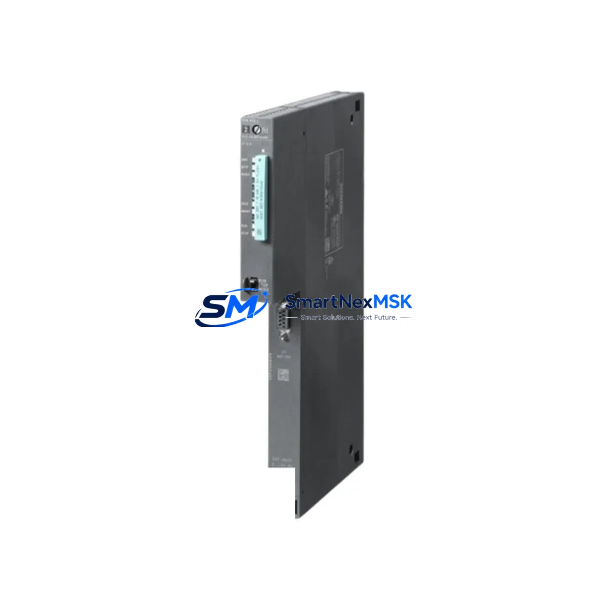
The Siemens 6ES7412-1XJ07-0AB0 is the CPU 412-1 central processing unit for the SIMATIC S7-400 programmable logic controller platform — one of the most widely deployed process automation architectures in heavy industry, power generation, chemical processing, and discrete manufacturing. As a maintenance-ready original spare, this module is sourced, inspected, and dispatched to support rapid field replacement, minimise unplanned downtime, and extend the operational life of installed S7-400 control systems.
For maintenance engineers managing aging S7-400 racks, the CPU 412-1 is a critical single point of failure. A failed or degraded CPU halts the entire control loop. Holding a verified spare — or sourcing one from a reliable industrial distributor with pre-shipment testing — is the most effective strategy for downtime recovery within a single maintenance shift. This unit ships with a 12-month warranty and is tested before dispatch to confirm firmware boot, backplane communication, and memory integrity.
Spare Maintenance Table
| Parameter | Specification |
|---|---|
| Part Number / SKU | 6ES7412-1XJ07-0AB0 |
| Module Type | CPU 412-1 — Central Processing Unit |
| Platform | SIMATIC S7-400 |
| Working Memory | 256 KB (expandable via memory card) |
| Load Memory | Integrated Flash + external MMC slot |
| Communication Interfaces | MPI / DP (integrated), supports PROFIBUS DP master |
| Backplane Bus | S7-400 universal rack (UR1, UR2, ER1, ER2) |
| Supply Voltage | DC 5 V via backplane (from PS 407 / PS 405 power supply) |
| Operating Temperature | 0 °C to +60 °C |
| Protection Class | IP20 |
| Country of Origin | Germany |
| Compatibility | SIMATIC S7-400 universal racks; STEP 7 V5.x / TIA Portal |
| Firmware Version | V7.0 (as per order suffix -0AB0) |
| Warranty | 12 Months — tested before shipment |
| Condition | Original, unused or refurbished-to-spec |
| Typical Application | Process control, DCS integration, batch automation, safety-adjacent systems |
Maintenance Planning for Continuous Operation
When a CPU 412-1 replacement is scheduled or triggered by a fault, experienced maintenance engineers treat the event as an opportunity for a broader control cabinet inspection. The S7-400 platform is a modular system, and the health of the CPU is interdependent with several surrounding components.
Begin with the PS 407 or PS 405 power supply module — the CPU’s backplane voltage source. A degraded power supply is a common root cause of intermittent CPU faults and should be load-tested before the new CPU is commissioned. Inspect the IM 460 / IM 461 interface modules if the rack uses expansion segments; a failing interface module can cause the CPU to report I/O errors that mimic CPU failure.
Review the SM 321 digital input modules and SM 322 digital output modules in the same rack. During a CPU swap, it is standard practice to verify that all I/O modules respond correctly to the new CPU’s initialisation cycle. Similarly, SM 331 and SM 332 analog I/O modules should be checked for channel drift or blown fuse indicators, particularly in high-cycle process environments.
If the system uses CP 443-1 or CP 443-5 communication processors for Ethernet or PROFIBUS DP connectivity, confirm that the network parameters stored in the CPU’s project data are correctly restored after the swap — especially if the replacement CPU carries a different firmware revision. For systems with FM 355 or FM 458 function modules handling closed-loop control or high-speed counting, re-validate the module parameters post-replacement.
Don’t overlook the SIMATIC S7-400 memory card (MMC) — the program and data backup medium. A corrupted or missing MMC is a frequent cause of failed CPU startups after replacement. Always keep a current, verified MMC backup as part of your spare parts kit alongside the CPU module itself. For sites running WinCC or SIMATIC HMI TP/MP panels connected via MPI, verify the HMI communication address assignments after the CPU is swapped to prevent operator screen loss.
Finally, inspect the terminal blocks, backplane connectors, and rack grounding straps. Oxidised or loose backplane contacts are a known failure mode in high-vibration or high-humidity environments and can cause the new CPU to exhibit the same symptoms as the failed unit.
Site Replacement Workflow
Step 1 — Pre-replacement preparation: Download and archive the current CPU program using STEP 7 or TIA Portal. Verify the MMC contains a current backup. Document the MPI address, DP master configuration, and any active hardware interrupts.
Step 2 — Safe isolation: Place the system in STOP mode via the mode selector switch. Confirm all outputs are de-energised and interlocks are in safe state. Follow site LOTO (Lockout/Tagout) procedures before opening the rack.
Step 3 — Module swap: Remove the failed 6ES7412-1XJ07-0AB0 by releasing the front panel locking screws and sliding the module out of the backplane slot. Insert the replacement module, ensuring the backplane connector seats fully. Tighten locking screws to the specified torque.
Step 4 — Program restore and commissioning: Insert the verified MMC. Power up the rack and observe the CPU’s RUN/STOP/ERROR LEDs. If the CPU starts in STOP with the MMC inserted, initiate a memory reset (MRES) and allow the program to load from the card. Confirm RUN mode is achieved before releasing the system to operations.
Step 5 — Post-replacement verification: Confirm all I/O modules are recognised in the hardware configuration. Check PROFIBUS DP slave status. Verify HMI communication. Run a short operational cycle and monitor for diagnostic buffer entries. Log the replacement in the site maintenance record.
This workflow is compatible with direct replacement of earlier CPU 412-1 variants. The -0AB0 firmware suffix ensures compatibility with STEP 7 V5.5 SP4 and above, as well as TIA Portal V13 SP2 and above in legacy mode.
Spare Parts Support FAQ
Q1: Is the 6ES7412-1XJ07-0AB0 compatible with all S7-400 racks?
Yes. The CPU 412-1 is designed for SIMATIC S7-400 universal racks (UR1, UR2) and expansion racks (ER1, ER2). It occupies a single slot and is compatible with all standard S7-400 power supply and I/O modules. Confirm your rack’s slot assignment and MPI address before installation.
Q2: What testing is performed before shipment?
Each unit undergoes power-on verification, backplane communication check, and firmware version confirmation prior to dispatch. Units are packed in anti-static ESD packaging with a test report. The 12-month warranty covers functional defects identified after installation under normal operating conditions.
Q3: Can this CPU replace an older 6ES7412-1XJ05-0AB0 or -1XJ06-0AB0 variant?
In most cases, yes. The -0AB0 suffix denotes the firmware generation. The hardware form factor and backplane interface are identical across the 412-1 family. However, projects compiled under older STEP 7 versions should be re-compiled and downloaded to the new firmware version to avoid compatibility warnings. Always verify with your site’s STEP 7 project version before committing to the swap.
Q4: What is your lead time and long-term supply availability?
Standard orders ship within 1–3 business days from verified stock. For planned maintenance programmes requiring multiple units or scheduled delivery windows, contact our sales team to arrange a supply agreement. We maintain ongoing stock of S7-400 CPU and I/O modules to support long-term system maintenance beyond the Siemens standard product lifecycle.
© 2026 SMARTNEXMSK. All rights reserved.
Original Source: https://smartnexmsk.com
Contact: sales@smartnexmsk.com | +86 18259474341


