Siemens 6GK1105-2AE00 Maintenance-Ready Spare for OSM Automation
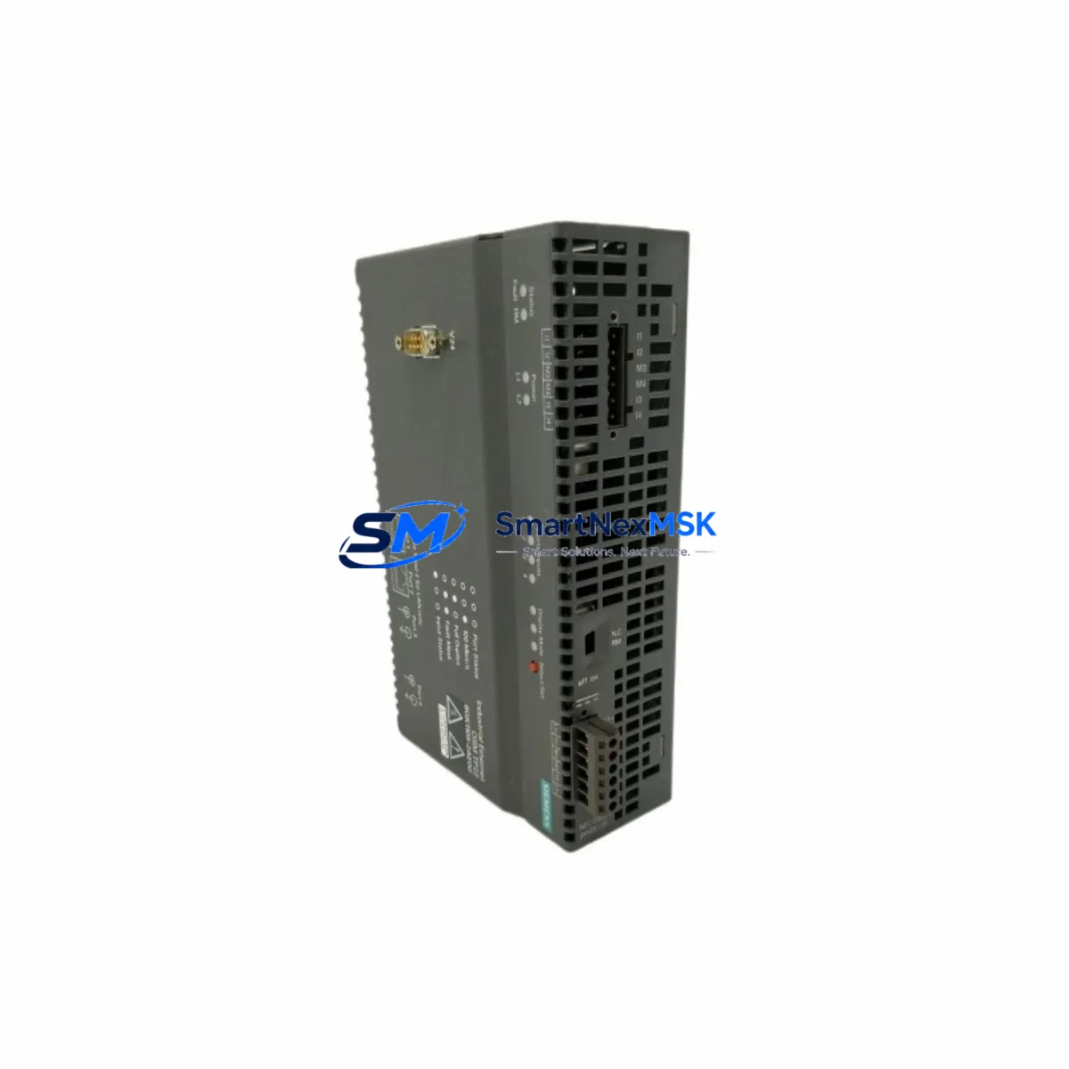
The Siemens 6GK1105-2AE00 is an original OSM TP22 (Optical Switch Module) designed for SIMATIC NET industrial Ethernet networks. As a managed 10/100 Mbit/s switch with fiber-optic and twisted-pair ports, it serves as a critical backbone component in ring-topology and linear-bus automation networks across manufacturing, process control, and infrastructure environments. When this module fails or reaches end-of-service life, unplanned downtime can cascade across entire production lines. Stocking a verified replacement unit is the most effective strategy for minimizing mean time to repair (MTTR) and protecting continuous operation.
This listing supplies a maintenance-ready, tested 6GK1105-2AE00 unit — sourced from authorized channels, inspected before dispatch, and backed by a 12-month warranty. Each unit ships with full functional verification to ensure drop-in compatibility with existing SIMATIC NET ring or star topologies.
Spare Maintenance Table
| Parameter | Specification |
|---|---|
| Part Number / SKU | 6GK1105-2AE00 |
| Product Family | OSM TP22 (Optical Switch Module) |
| Series | SIMATIC NET Industrial Ethernet |
| Switch Type | Managed, Layer 2 |
| Port Configuration | 2 × fiber-optic (SC/ST), 2 × RJ45 10/100 Mbit/s |
| Data Rate | 10/100 Mbit/s |
| Topology Support | Ring (MRP/HRP), Linear Bus, Star |
| Supply Voltage | 24 V DC (18–32 V DC operating range) |
| Power Consumption | Approx. 5 W |
| Operating Temperature | -10 °C to +60 °C |
| Protection Class | IP30 |
| Mounting | DIN rail (35 mm) |
| Dimensions (W×H×D) | Approx. 60 × 125 × 75 mm |
| Weight | Approx. 2,100 g (packaged) |
| Country of Origin | Germany |
| Compatibility | SIMATIC NET OSM/ESM series; S7-300/400 PLC networks; ET 200 distributed I/O |
| Certifications | CE, UL, ATEX (zone-dependent) |
| Warranty | 12 Months — tested and verified before dispatch |
| Maintenance Recommendation | Inspect fiber connectors and power terminals every 12 months; replace if link-loss alarms persist |
Maintenance Planning for Continuous Operation
When a 6GK1105-2AE00 OSM TP22 is flagged for replacement during a scheduled shutdown or emergency callout, experienced maintenance engineers know that the switch itself is rarely the only component requiring attention. A thorough inspection of the surrounding electrical and communication infrastructure is essential to prevent repeat failures and ensure the restored network performs reliably.
Begin with the 24 V DC power supply feeding the OSM — units such as the Siemens SITOP PSU100S 24 V/5 A or equivalent DIN-rail power supplies should be load-tested and checked for output ripple before the new switch is commissioned. Verify that the power terminal blocks (e.g., Phoenix Contact or Weidmüller screw-clamp terminals) show no signs of oxidation or loose torque, as poor contact at the 24 V input is a leading cause of intermittent switch resets.
Inspect all fiber-optic patch cables and SC/ST connectors connected to the OSM TP22. Contaminated or cracked fiber ends cause link-loss events that are frequently misdiagnosed as switch failure. Clean connectors with an appropriate fiber cleaning kit and measure optical power budget with an optical power meter before declaring the cable serviceable. If the OSM is part of a PROFINET MRP ring, also verify the ring manager configuration on the adjacent SCALANCE X-series switches (e.g., SCALANCE X208 or X216) to confirm ring redundancy is restored after the swap.
For sites running Siemens S7-300 or S7-400 PLCs with CP 343-1 or CP 443-1 communication processors, confirm that the PLC’s Ethernet interface retains its IP configuration and that the PROFINET device name is correctly assigned after the switch replacement. Check the ET 200S or ET 200M distributed I/O nodes downstream of the OSM for any persistent diagnostic alarms in STEP 7 or TIA Portal — these may indicate that I/O modules lost their parameterization during the network outage.
While the control cabinet is open, it is good practice to inspect 24 V relay output modules (such as Siemens 6ES7 132-series digital output modules) and signal isolators or barriers in the same cabinet section. Surge events that damage network switches often stress adjacent components. Check miniature circuit breakers (MCBs) and fuse holders on the 24 V distribution rail for signs of thermal stress. If the site uses a Siemens OP/TP HMI panel (e.g., TP700 Comfort or KTP900 Basic) connected through the same Ethernet segment, verify that the HMI re-establishes its connection to the PLC after the OSM is replaced and that no project download is required.
Finally, update the site’s spare parts register to reflect the replacement and log the fiber connector cleaning date, power supply output voltage, and ring redundancy test result. A documented maintenance record supports both ISO 9001 compliance and future troubleshooting efficiency.
Site Replacement Workflow
Step 1 — Isolate and de-energize: Notify the control room, place the affected PLC in STOP mode if safe to do so, and de-energize the 24 V supply to the OSM TP22 via the upstream MCB. Do not disconnect fiber cables under power if SFP transceivers are present in adjacent equipment.
Step 2 — Document existing wiring: Photograph or sketch the fiber port assignments (ring port A/B, downlink ports) and the 24 V terminal connections before removal. The 6GK1105-2AE00 uses a fixed port layout; however, confirming the ring direction prevents misconfiguration on restart.
Step 3 — Remove the failed unit: Release the DIN-rail latch, disconnect the 24 V terminals, and carefully unplug the fiber connectors. Cap all fiber ends immediately with dust caps to prevent contamination.
Step 4 — Install the replacement unit: Clip the new 6GK1105-2AE00 onto the 35 mm DIN rail, reconnect the 24 V terminals to the correct polarity (observe the L+/M labeling), and reconnect the fiber cables in the same port positions as documented in Step 2.
Step 5 — Power-on and verify: Energize the 24 V supply and observe the OSM’s LED indicators. The LINK LEDs on active ports should illuminate within 30 seconds. If the unit is part of an MRP ring, the ring manager on the adjacent SCALANCE switch should report “Ring closed” status. Confirm in TIA Portal or STEP 7 that all PROFINET devices are online and that no I/O alarms are active.
Step 6 — Functional test and handover: Run a brief production cycle or simulate I/O signals to confirm end-to-end network communication. Record the replacement in the maintenance log, attach the 12-month warranty documentation, and return the failed unit for failure analysis if required by site procedures.
Spare Parts Support FAQ
Q1: Is the 6GK1105-2AE00 still available as a new original spare, or only as a refurbished unit?
We supply original Siemens 6GK1105-2AE00 units sourced from authorized distribution channels. Each unit undergoes functional testing — port link verification, power-on self-test, and fiber optical path check — before dispatch. A 12-month warranty is provided on every unit shipped.
Q2: How do I confirm compatibility with my existing SIMATIC NET ring topology before ordering?
The 6GK1105-2AE00 is compatible with all OSM TP22-based SIMATIC NET ring and star topologies, including systems managed by SCALANCE X-series switches and S7-300/400 CP modules. If your site uses a non-standard fiber wavelength or connector type, please share your existing OSM order code or network diagram with our technical team at sales@smartnexmsk.com before placing the order.
Q3: What is the lead time, and can you support urgent breakdown orders?
Standard orders are processed and dispatched within 1–3 business days. For emergency breakdown situations, contact us directly at +86 18259474341 to confirm real-time stock availability and expedited shipping options. We maintain buffer stock of high-demand SIMATIC NET components specifically to support unplanned downtime scenarios.
Q4: What does the 12-month warranty cover, and what is the return process?
The 12-month warranty covers manufacturing defects and functional failures under normal operating conditions (within the specified voltage, temperature, and environmental ratings). It does not cover damage caused by incorrect installation, overvoltage, or physical impact. To initiate a warranty claim, contact sales@smartnexmsk.com with your order number, a description of the fault, and any available diagnostic data (LED status, TIA Portal alarms). We will arrange collection and replacement or repair within the warranty period.
© 2026 SMARTNEXMSK. All rights reserved.
Original Source: https://smartnexmsk.com
Contact: sales@smartnexmsk.com | +86 18259474341


